Dynamic Grid – Row Split
This feature is used to split a row in a dynamic grid based on its index (column and row). Below are the steps to achieve that. In a real time scenario, consider a case where the employees have to enter their daily records. The information’s are entered into a dynamic grid. We use a new feature in dynamic grid called row split. While using the dynamic grid row split a single row can be further split into various numbers of rows so that the information can be clear. The employees address is provided in different rows inside a single row as well as employee’s name. With the dynamic grid row split the information’s of a particular user can be provided in a single row as well as it can be displayed clearly.
Dynamic Grid – Configuration.
Step 1: Select the Designer as shown in Figure 1.

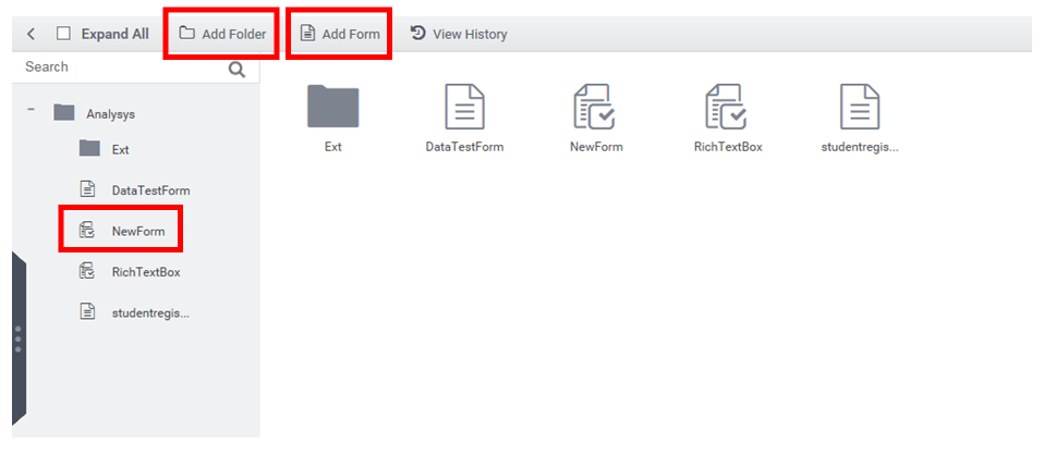
Step 2: Create a New Folder and within that folder create a New Form.
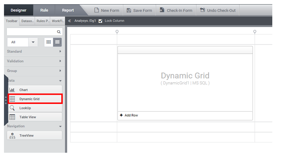
Step 3: As shown in the figure 3, in the ‘Data’ from the ‘Toolbox’, select the Control ‘Dynamic Grid’ and create a form.
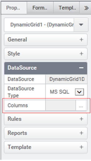
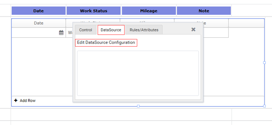
Step 4: Configure the dynamic grid with a Data Source. This can be done by fig 4 or by fig 5.
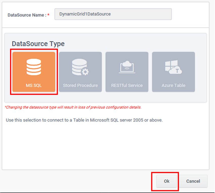
Step 5: Select the data source type from the ‘Data Source Type Select’ window and click the ‘Ok’ button.
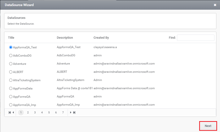
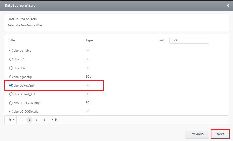
Step 6: Select DataBase and click on ‘Next’ button and select the table from the ‘Dynamic Grid Configuration’ window.
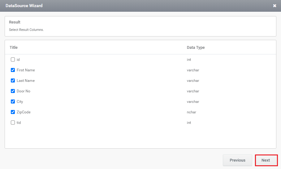
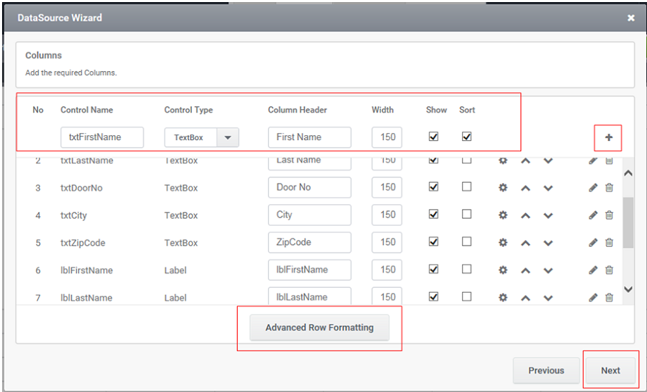
Step 7: Select the columns required from corresponding table.
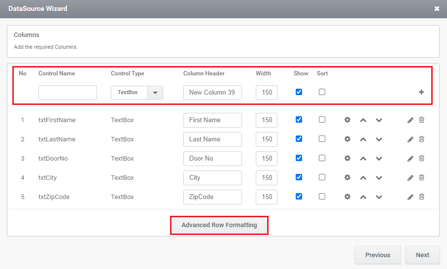
Step 8: Select ‘Advanced Row Formatting’ button in the ‘Dynamic Grid Configuration’ window so that the DG- Row split can be implemented.
Dynamic Grid – Row split
The basic difference between the Dynamic Grid and the new feature, Dynamic Grid – Row Split is an enhanced view of Data entered into the grid.
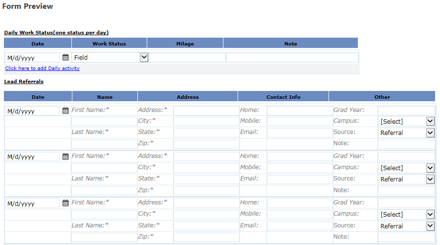
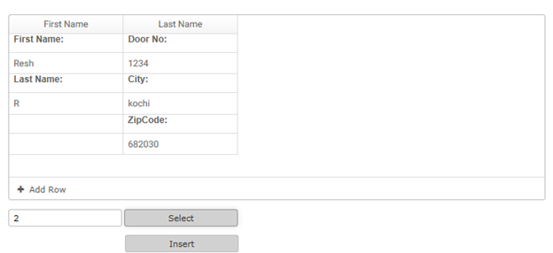
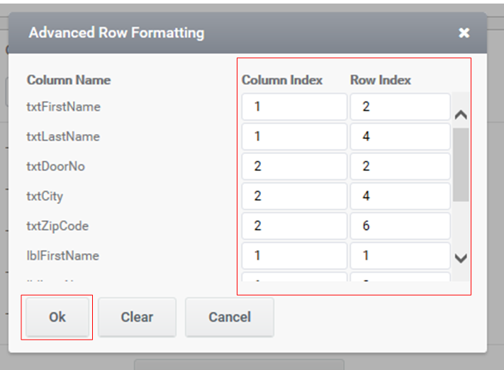
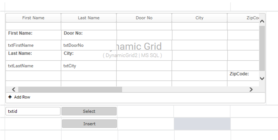
Step 8:The data inside the Dynamic Grid can be re-arranged as per the user’s convenience based on the numbers entered into the column index and row index. As seen in the below example, the preview is achieved by entering the values 1 and 1 in both the column and row index respectively so that the data is positioned in the left-topmost cell of the table. Thereby in-order to enter a value in the leftmost 2nd cell of a table, the value is entered in a format of 1st column and 2nd row. Thus the formats continue and later click on the ‘Ok’ button. Consider the example of last name in our form, the row index and column index are given as 2nd and 2nd. Here the last name is in the 2nd row of the row Name, thus the row index is given as 2nd. And the column index is also given as 2nd because the textbox for entering the name comes 2nd in the second row as the label for the textbox would come in the 1st column.
Command Configuration
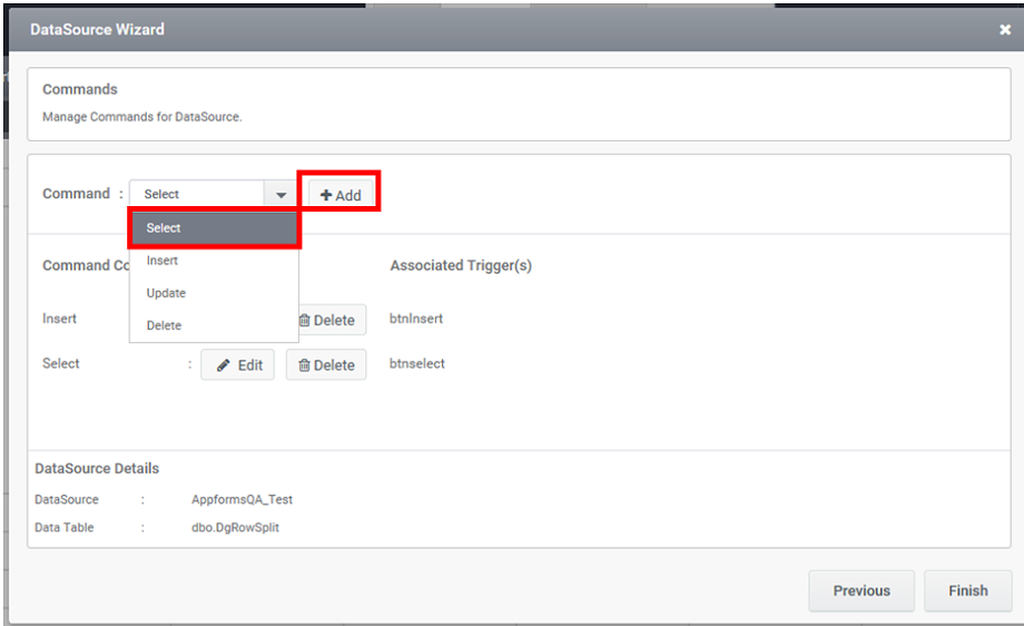
Step 10: Here, in the below given scenario, the commands, Select and Insert are configured. After Step 9, in the ‘Dynamic Grid Configuration’ window opt the command ‘Select’ from the combo box and click on the ‘Add’ button.
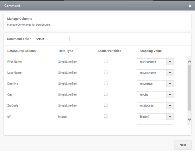
Step 11: In the appeared window, map the columns to the control names and then click ‘Next’ button.
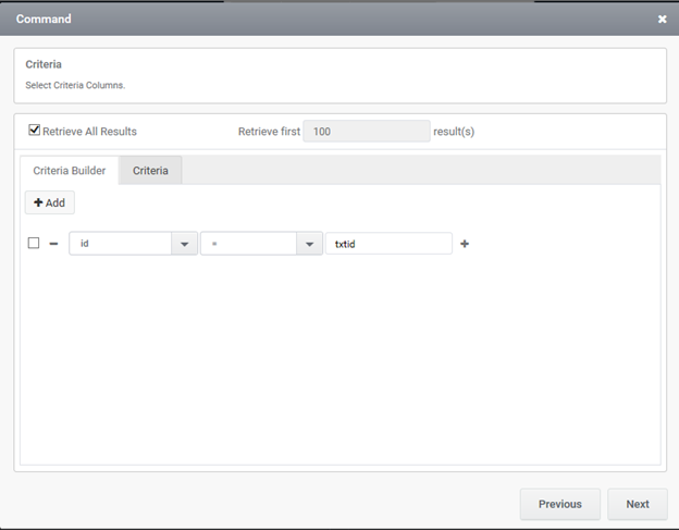
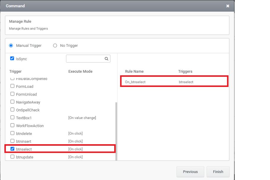
Step 12: After mapping the columns, click on the ‘Next’ button and set the criteria(Figure 15). As shown in figure 16, select the trigger and click on the ‘Finish’ button. Thus the selected trigger will be mentioned below the ‘Associated Triggers’ and then click on the ‘Finish’ button.
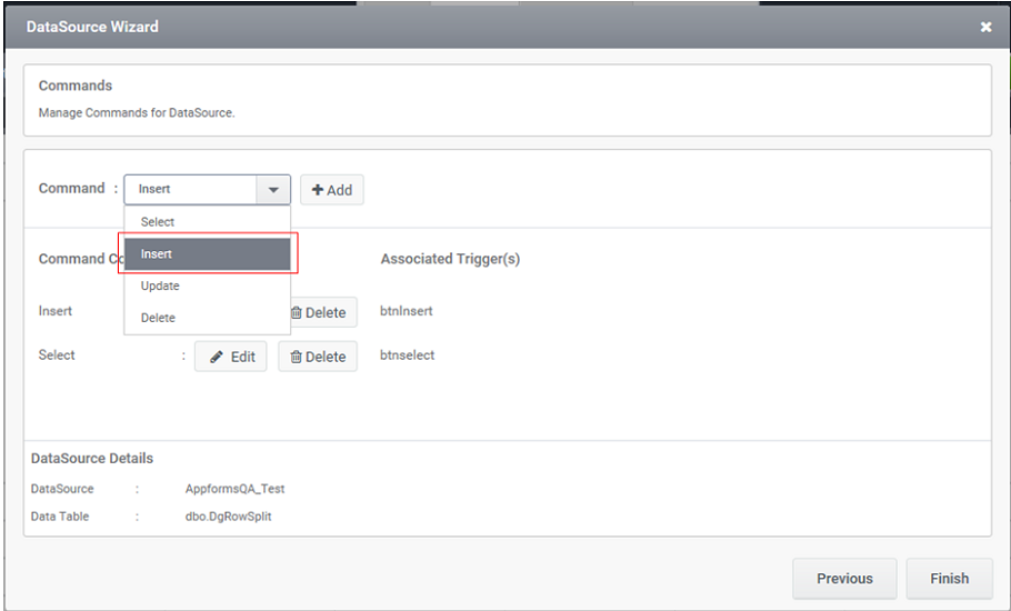
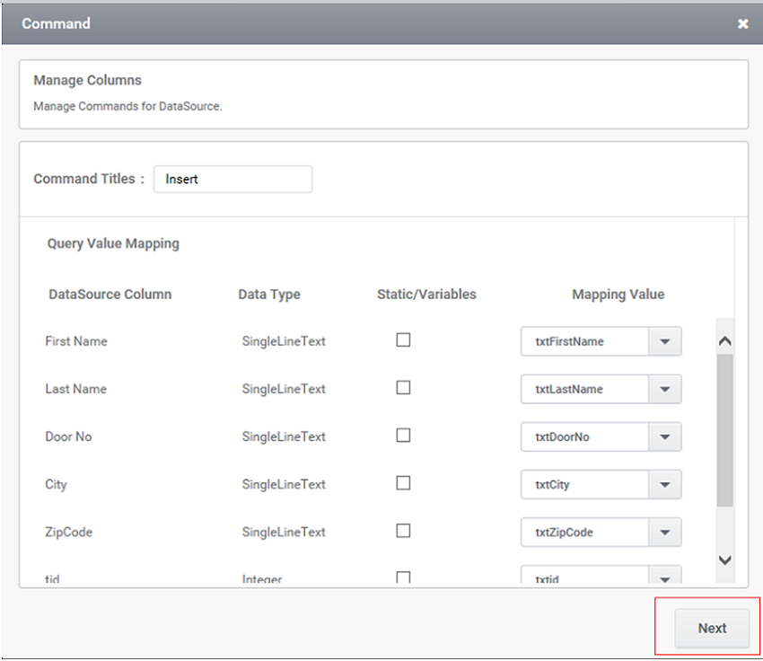
Step 13: Later (if required) opt the command ‘Insert’ from the combo box and click on the ‘Add’ button and as shown in figure 17,in the appeared window map the columns to the control and click on the ‘Next’ button.
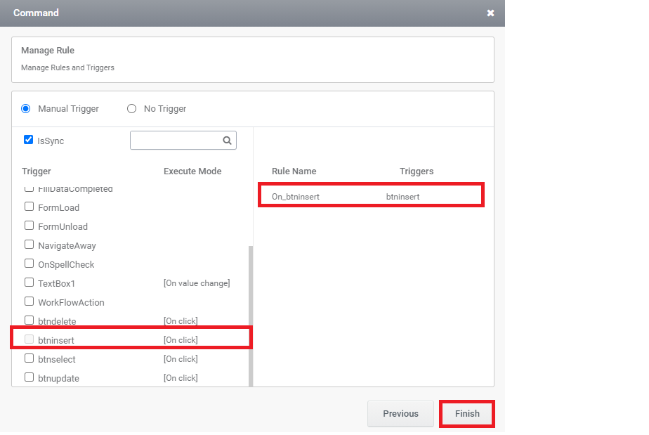
Step 14: After mapping the columns, select the trigger and click on the ‘Finish’ button. Thus the selected trigger will be mentioned below the ‘Associated Triggers’ and then click on the ‘Finish’ button.
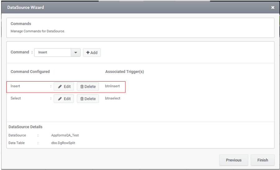
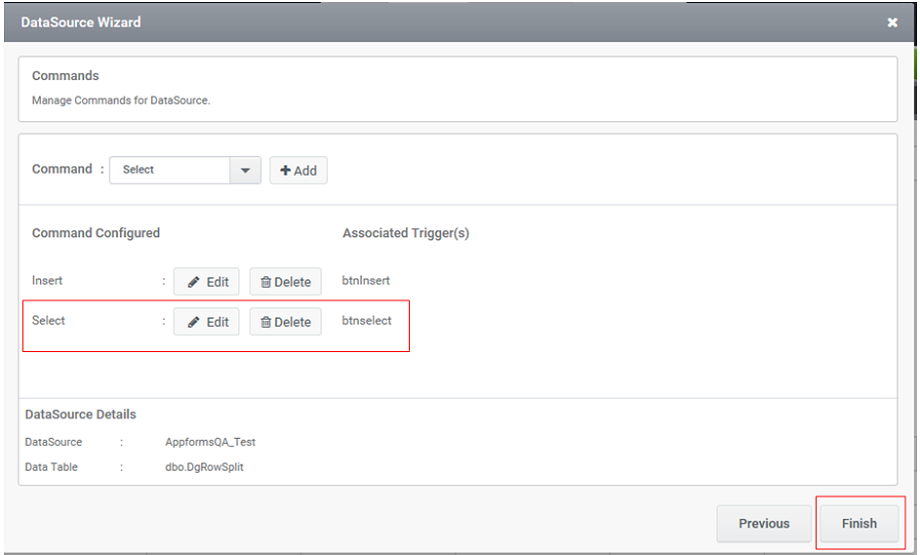
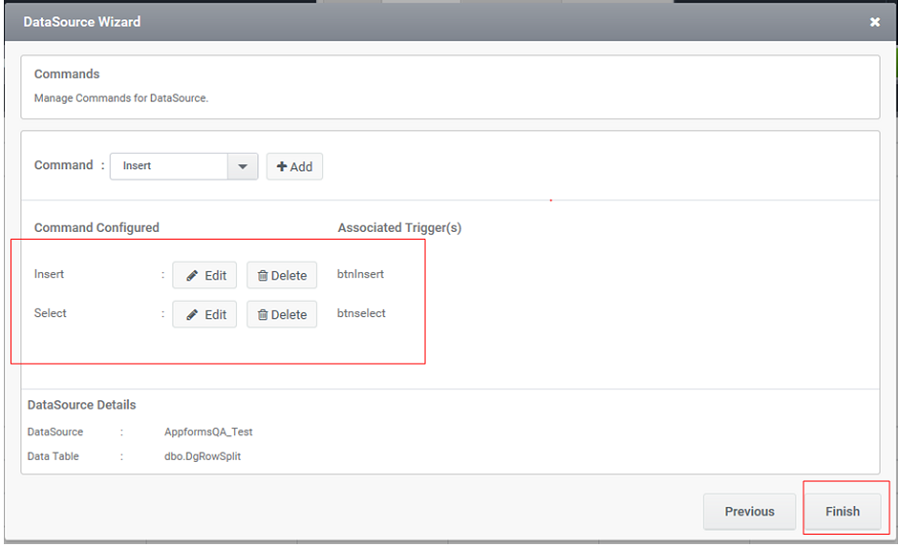
Step 15: In the ‘DynamicGrid Configuration’ window the configured commands will be listed below the ‘Command Configured’ section . After completing all the necessary command configuration (Update and delete if required), click on the ‘Finish’ button.
Output
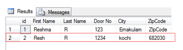
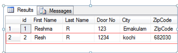
Step 16: In figure 21, on clicking the button ‘Insert’ configured for Insert command enable the user to insert the values into the table (Figure 22)
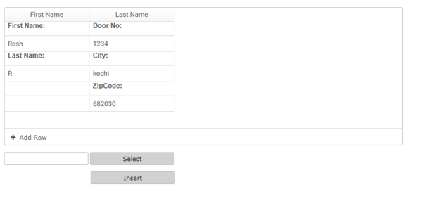
Step 17: In figure 23, on clicking the button ‘Select’ configured for Select command, enable the user to view or select the values from the list (Figure 24), based on the given ‘ID’ in the Form.