ClaySys AppForms Version 1.0
Introduction to WSDL ( Web Service Definition Language )
WSDL is an XML format for describing network services as a set of endpoints operating on messages containing either document-oriented or procedure-oriented information. The operations and messages are described abstractly, and then bound to a concrete network protocol and message format to define an endpoint. Related concrete endpoints are combined into abstract endpoints (services). WSDL is extensible to allow description of endpoints and their messages regardless of what message formats or network protocols are used to communicate, however, the only bindings described in this document describe how to use WSDL in conjunction with SOAP 1.1, HTTP GET/POST, and MIME.
A WSDL document defines services as collections of network endpoints, or ports. In WSDL, the abstract definition of endpoints and messages is separated from their concrete network deployment or data format bindings. This allows the reuse of abstract definitions: messages, which are abstract descriptions of the data being exchanged, and port types which are abstract collections of operations. The concrete protocol and data format specification for a particular port type constitutes a reusable binding. A port is defined by associating a network address with a reusable binding, and a collection of ports define a service. Hence, a WSDL document uses the following elements in the definition of network services:
Types– a container for data type definitions using some type system (such as XSD).
Message– an abstract, typed definition of the data being communicated.
Operation– an abstract description of an action supported by the service.
Port Type–an abstract set of operations supported by one or more endpoints.
Binding– a concrete protocol and data format specification for a particular port type.
Port– a single endpoint defined as a combination of a binding and a network address.
Service– a collection of related endpoints.
Configuring the WSDL and Reading the available web methods
- The basic requirement will be that the ClaySys AppForms application should be able to access any external web service and allow the application to make calls to it.
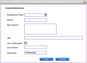
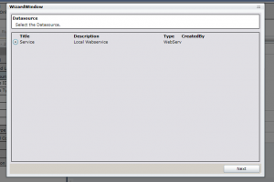
- When a new WSDL is introduced to the application, the end user will be adding the URI of the WSDL to the application along with the Credentials if any.
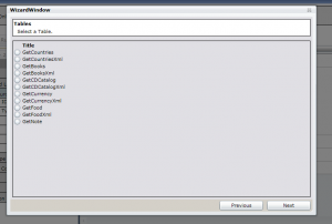
- Once the URI and credentials are provided, the application will display all the web methods available from the WSDL.
- When the user selects one web method, the application will display the parameters that need to be passed to this web service and the return type of the web service.
- In case of a single value, the admin user can assign the return value to a Control in the form.
- In case of an xml, he will be able to pass the node values to more than one Control in the form.
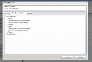
- If the return type is XML, then the admin user will have to execute the web method once with a valid parameter, so that the application can get a sample XML which can be used for the configuration.
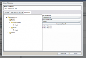
- Once the application gets a sample xml, the admin can map each node of the xml to any of the controls in the form. This can also be mapped to the datasource of a combo box or lookup etc.
-
- Real-time execution
- Queuing
The WSDL Configuration steps are explained below
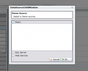
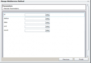
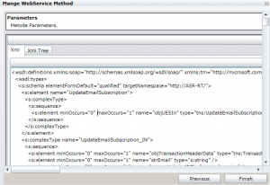
In case of a XML parameter the administrator will be able to define the XML parameter structure. If there is a XML file that contains the syntax of the parameter to the web method, it can be imported to the ClaySys AppForms application or the administrator can define the xml using the following screen. The screen will be opened when the administrator will click on the button named XML next to the parameter textbox.
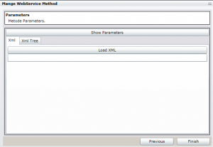
Once the administrator user clicks on the button named “Load XML” it will allow the administrator to open an xml file, the second option is to define the XML manually.
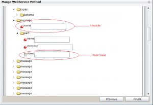
After defining the XML syntax for the parameter, the administrator will be able to map the controls in the form, global variables or session variables to each node value or attribute of a node. This option will be available when the tab XML Tree is clicked.
Configuring the return type to a form
The return type of a web service can be a single value or a XML.
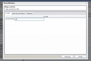
Dynamic Invocation of Web Methods
The ClaySys AppForms rendering engine will be able to invoke the web method dynamically. There will be a proxy WFC which will be used by the ClaySys AppForms application. The ClaySys AppForms application will only make call to this WCF service which in turn will make the dynamic call to the third party WSDL files from the server.
Each web service call details will be saved to a transaction table irrespective of the output. The details saved will be timestamp of the call, parameters, return value, etc.
Failures and Timeouts
Each WSDL call will be having a timeout period, which will be set to 5000 milliseconds (5 Seconds) by default. When the WSDL timeouts, the datasource will either send the error code to the client or read the values from the database (which can be configured when the datasource is details are saved). The status of the WSDL execution will be passed to the client.
Exception Handling
The WSDL configuration will allow user-friendly exception messages to be passed from server to the client. The exception, with the details like Timestamp, User Name, etc. will also be logged to an Exception table so that it can be checked in later stage.
This module will be using the generic exception handling method that is supported in ClaySys AppForms application for logging the errors to the exception table and sending the user a user friendly error message.
WSDL Execution Approaches
Real-time execution
In this approach the WSDL will be invoked at real time. There will be a proxy ClaySys AppForms service which will be used to invoke any WSDL from the server at real-time. The client will not make the WSDL call directly and will always be using the Proxy service.
Queuing
In this model, the ClaySys AppForms application will be using the default datasource to save the data to a SQL table. There will be a server side windows workflow service, which will be doing a data pooling to this table. Each time it finds a new record, the service will read the record and post it to the WSDL. The timeout, exception handling will be logged to the table which will be similar to the real-time execution.
Attaching Procedure Call
For each WSDL configured, there can be a procedure call at each successful execution. The procedure call can be another WSDL or a stored procedure which will consume the output of the existing WSDL to do some other activities like merging the records.