Maintaining high availability and setup disaster recovery in ClaySys AppForms

ClaySys AppForms High Availability Configuration

This blog will present the High Availability options available to deploy the ClaySys AppForms Solution onto an infrastructure, with the right operational procedures that can provide 24/7 ClaySys AppForms System Availability.
The High Availability Architecture described in this section, once combined with the right Operational Procedures and Resources, will ensure that Client Maintains a very high level of service uptime.
Note that, the Microsoft High Availability Technology Options enables seamless failover and load balancing, without needing manual intervention for executing the failover or transferring Network Traffic Load. But proper Operational Procedures need to be in place, to ensure appropriate testing, software maintenance etc.
To understand the ClaySys AppForms System High Availability Configuration, first we going to review on architecture for High Availability with the SQL Server Database and then we will review on High availability configuration for the ClaySys AppForms Application Servers.
ClaySys AppForms Database – High Availability
SQL Server 2008 64 bit (Std or Ent) will be installed and configured for the ClaySys AppForms Solution.
With SQL Server, Microsoft has two options available for maintaining a high availability configuration. They are SQL Server Failover Clustering and Database Mirroring.
Failover clustering is a tried and tested technology that uses a shared storage (usually a SAN) between two or more SQL Server nodes that are on different physical servers.
There are two weaknesses with this approach, which are that the SAN can become a single point of failure, and that failing over from one node to another (E.g. For scheduled maintenance), can take one to two minutes on a busy cluster. This can make it much more difficult to achieve five nines availability, since just applying monthly Microsoft security patches onto each node, and then failing over will probably eat up the six minutes per year of down time with 99.999 availability.
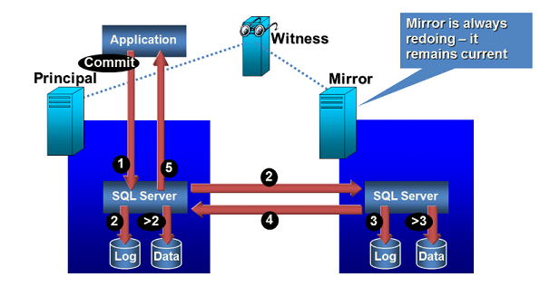
The alternative that is now becoming more and more popular is for organizations to use Database Mirroring instead of clustering. With database mirroring, you are mirroring at the database level and not the instance level. You will have a principal database and a mirror database, each running on a different server, with its own dedicated storage. This scenario eliminates the single point of failure of the shared storage, and also gives you the ability to failover in 10-15 seconds.
The only downside is that you will need twice the storage space. It also requires a third server to be the Witness server if you want to run in Synchronous mirroring mode with automatic failover. The witness server can run SQL Server Express Edition and can be a low-end server, which can help on the cost front. If the Witness Server goes down, then the only impact is, we have to manually manage the Failover from the Principal to the Mirror Server.
The presentation below presents the summary of how SQL Server Mirroring works and the schematic below gives a brief understanding as well:
SQL Server Mirroring
To understand how exactly mirroring works, please also go through the detailed documentation on the Microsoft website, using the link below:
https://msdn.microsoft.com/en-us/library/bb934127.aspx
ClaySys AppForms Application Server – High Availability
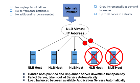
The ClaySys AppForms Application Server will be installed on Windows Server 2008 64 bit edition. We will be setting up a Network Load Balanced cluster of multiple ClaySys AppForms Application servers, to meet Scalability and High Availability requirements for the Client.
Network Load Balancing (NLB) is a way to configure a pool of machines so they take turns responding to requests. It’s most commonly implemented in server farms with identically configured machines that spread out the load for a web application. It can also be used for a firewall (ISA) farm, VPN access points etc.
Anytime you have TCP/IP traffic, that has become too much load for a single machine, but you still want it to appear as a single machine for access purposes, is when NLB becomes an appropriate fit.
NLB works in the following manner:
After you install NLB on a server, you add two or more machines to a NLB Cluster. The machines are configured with 2 IP addresses: their own private unique one, and a second one that is shared by all the machines in the cluster.
The machines all run an algorithm that determines whose turn is next at responding to requests. They also exchange heartbeats with one another, so they all know if one server goes down and won’t allocate any more requests to it.
You can configure how requests are allocated. You can set up affinity so that requests from one subnet will be responded to from Server A whenever possible, and that other subnets prefer Server B. Also you could setup 80% of all incoming requests to be handled by Server A, with the rest going to server B.
There are a few other things you can do with affinity:
Single affinity: connections initiated by a given IP address are handled by the same server in the cluster until cluster membership changes.
No affinity: connections are load-balanced based on originating address and port. This is more efficient, as connections from the same client can be routed to several hosts.
VPN and IPSec affinity: vpn and ipsec sessions will be preserved even if cluster membership changes.
Class C affinity: useful when internet clients access the cluster through proxies that expose the same class-C addresses. Load balancing is based on the class-C subnet portion of the incoming address.
The presentation below presents the summary of how NLB works and the schematic below gives a brief understanding as well:
Network Load Balancing Schematic
To understand how exactly NLB works, please also go through the detailed documentation on the Microsoft website, using the link below:
https://technet.microsoft.com/en-us/library/cc770625(WS.10).aspx
*Note: The combination of NLB and SQL Server Mirroring will ensure 24/7 High Availability for ClaySys AppForms Services. These technology options will have to be supported by Operational Processes that ensure the right resources are available for maintenance of the ClaySys AppForms Services, and for supporting the Microsoft High Availability options presented in this architecture.
ClaySys AppForms Disaster Recovery Setup

This section highlights how ClaySys AppForms Disaster Recovery can be setup at the Client, to ensure that a warm standby server infrastructure is being maintained at a separate Disaster Recovery Center.
So in the event of the ClaySys AppForms Services becoming unavailable form the primary ClaySys AppForms Hosting Service. There could be immediate transition of ClaySys AppForms Services to the Disaster Recovery Infrastructure.
ClaySys AppForms Disaster Recovery through Log Shipping
In this scenario, a Disaster Recovery (DR) Server Infrastructure will be maintained by the client at a separate DR site. The application servers will have the same version of the ClaySys AppForms Software installed for both the OS as well as ClaySys AppForms Application.
The DR is maintained in synch with the production ClaySys AppForms, by synchronizing the Database at the DR site with the database of the Production site in near real time.
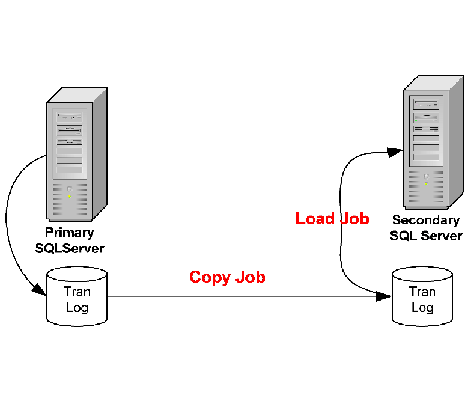
Log shipping is the process of automating the backup of database and transaction log files from a production SQL Server, and then restoring them onto a standby SQL Server at a DR site. The key feature of log shipping is that it will automatically backup transaction logs throughout the day (for whatever interval you specify) and automatically restore them on the standby DR SQL Server. This in effect keeps the two SQL Servers in synch. So should the production server fail, all you have to do is point the users to the new server, to resume services.
Note that there will always be the tail end of the SQL Database Log files from the Production server that will need to be restored onto the DR Server, if you want to prevent any data loss prior to resumption of services.
In case there is a catastrophic failure at the Production SQL Server environment, and there is no availability of the tail end of the Database logs, then the maximum risk of Data Loss is as of the last shipment of the transaction log files to the DR Server. Log shipping frequency can be set to minutes, to ensure a minimal data loss in such a scenario.
The schematic below shows how the SQL Transaction Logs from the Primary SQL Server (Production Environment) are backed up onto a Secondary SQL Server at the client DR Site:
 To understand how exactly SQL Server log shipping works, please also go through the detailed documentation on the Microsoft website, using the link below:
http://msdn.microsoft.com/en-us/library/ms187103.aspx
Get Started with our Appforms Development Services
Blogs by Category
AppForms Artificial Intelligence Blockchain Call Centers Chatbots Cloud Computing Data Management Design Digital Marketing Digital Transformation Enterprise Applications FinTech Insights LowCode Development Microsoft Mobile Apps News Office 365 Robotic Process Automation Security SharePoint Software Development Web ApplicationTop Use Cases of AI Agents Transforming Business in 2026
2026-06-29 15:16:38