Design Document for Sales Viewer
Introduction
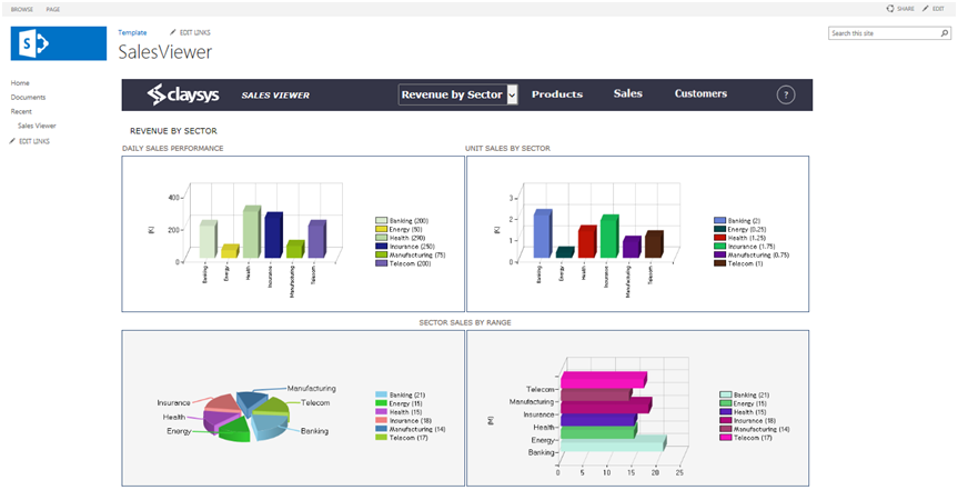
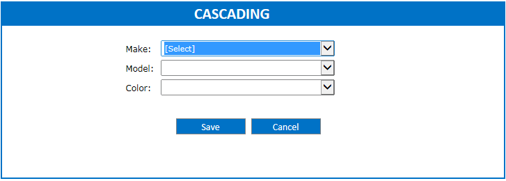
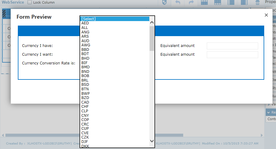
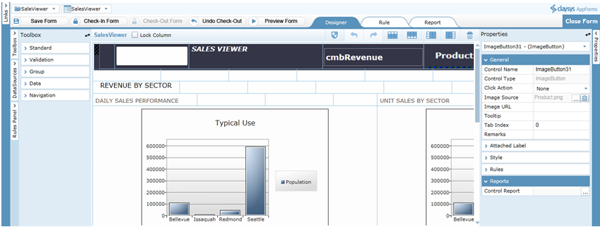
Sales Viewer has been designed to generates graphical reports on Daily sales performance, unit sales and sales by range on the basis of Revenue by sector and Revenue by product. The purpose of this document is designed to be a reference for any person wishing to implement or any person interested in the architecture of sales viewer for the ClaySys AppForms.
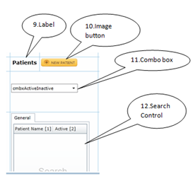
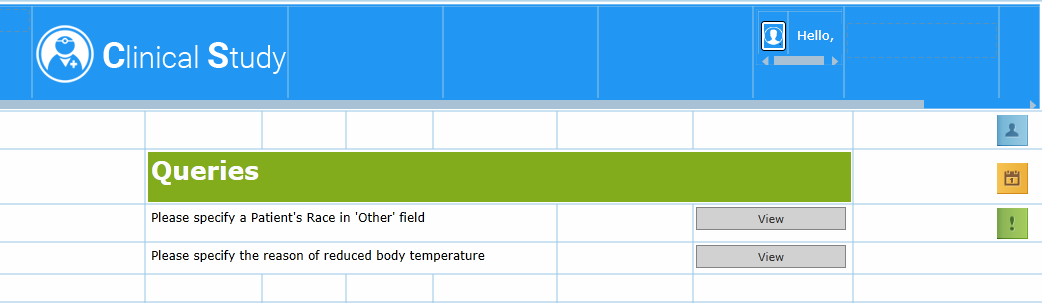
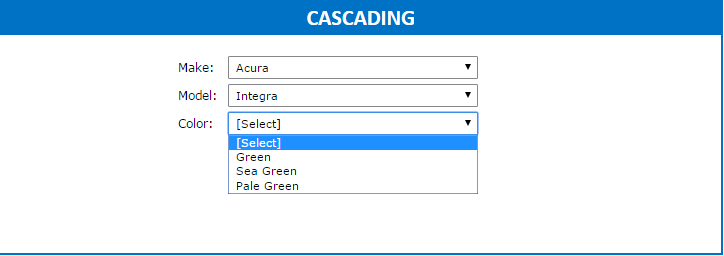
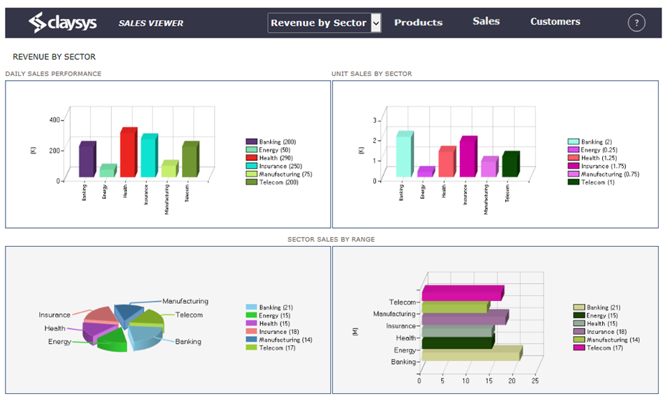
In ClaySys AppForms Sales Viewer , a combo box is available to select the category. If we select the category as Revenue by sector, the statistical report will shows the Daily sales performance, unit sales by sector and sector sales by range as shown in the below figure.
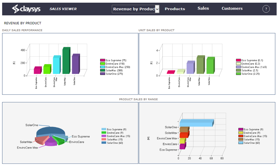
If we select the category as Revenue by Product, then the statistical report will shows the Daily sales performance, unit sales by product and Product sales by range as shown in the figure.
It is designed to guide development and design in ClaySys AppForms, including:
- Creating the form
- Form design
- Data Source configuration
- Rules
- How to use this template
- Uploading List Templates
- Import tenant
- Create a web part page
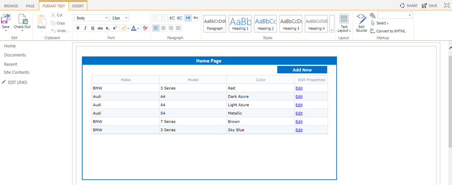
Creating the form
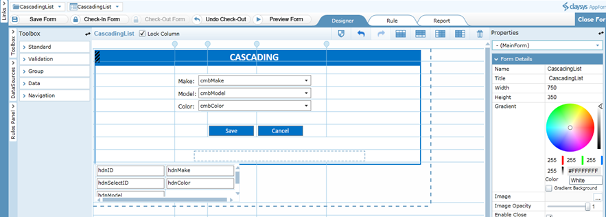
Form Design
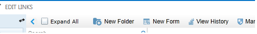
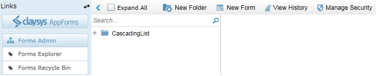
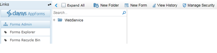
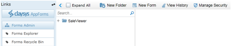
- On clicking the New Folder option, it will create a new folder and the name will be in the edit mode. You can type a new name for the folder.
- Then click on the ‘New Form’ link on the toolbar. Give an appropriate name for the form. Click ‘Save’ to save the form.
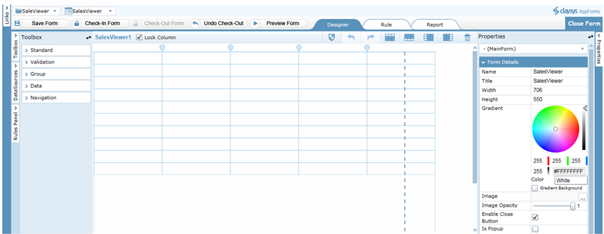
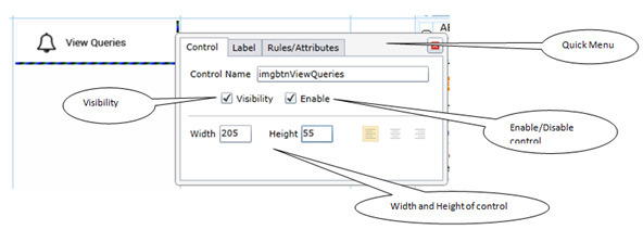
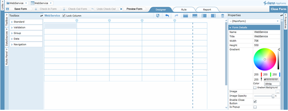
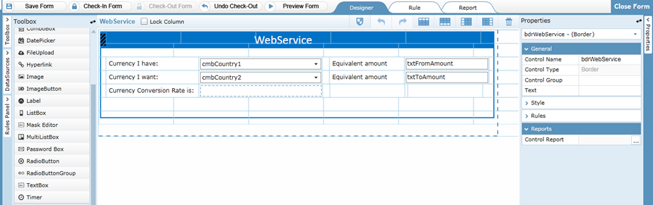
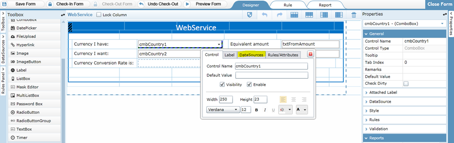
- You can drag and drop controls format the styles easily.
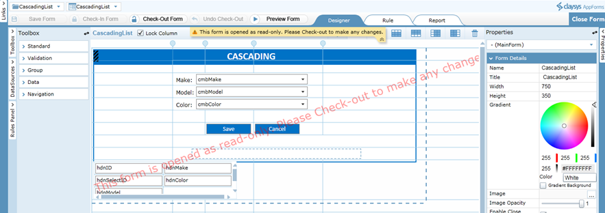
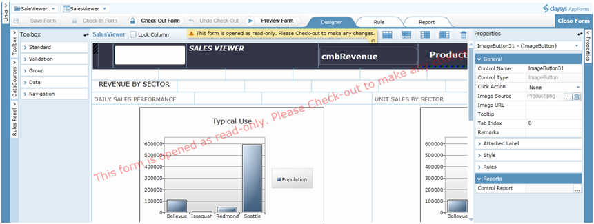
- ‘Check-In Form’ to save the changes and publish to get the completed form for the end user to use. A form must be checked-out to make modifications while all aspects of the form can be examined while checked-in.
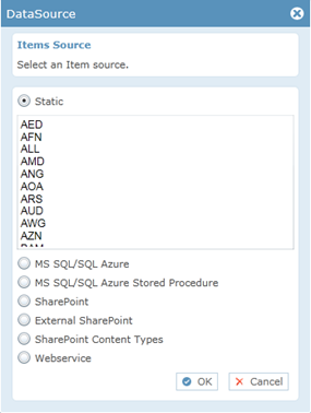
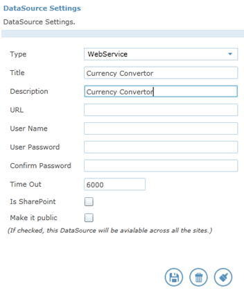
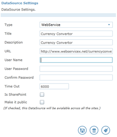
DataSource Configuration
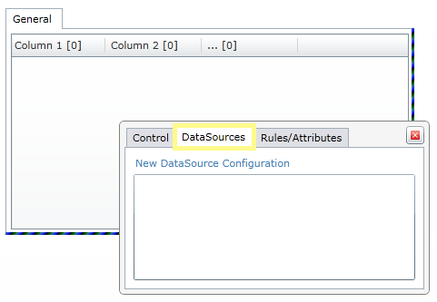
Following steps will explain about the DataSource configuration of Search control.
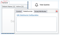
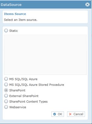
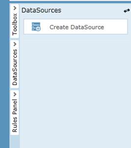
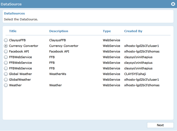
- Click Search control select the New DataSource Configuration.
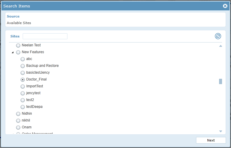
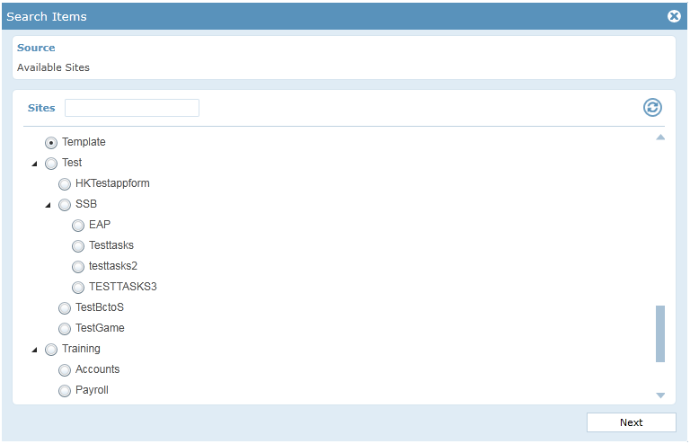
- Select the site from the available sites. Click ‘Next’ to continue.
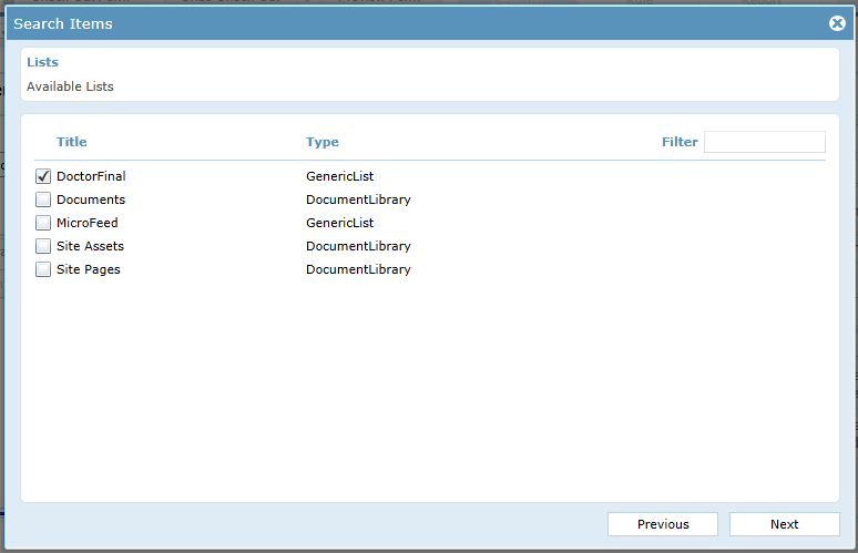
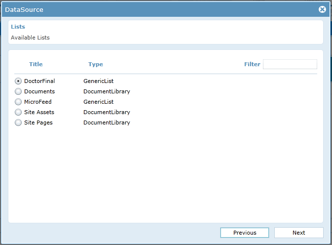
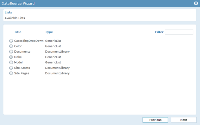
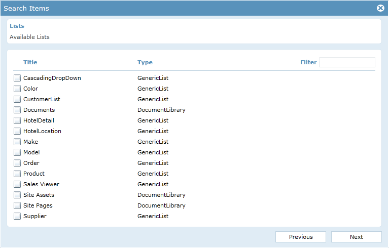
- Select the list from available list name. Click ‘Next’ to continue.
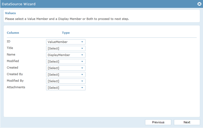
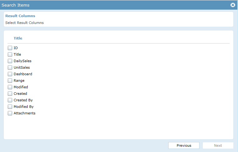
- Select the result columns. Click ‘Next’ to continue.
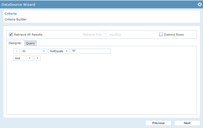
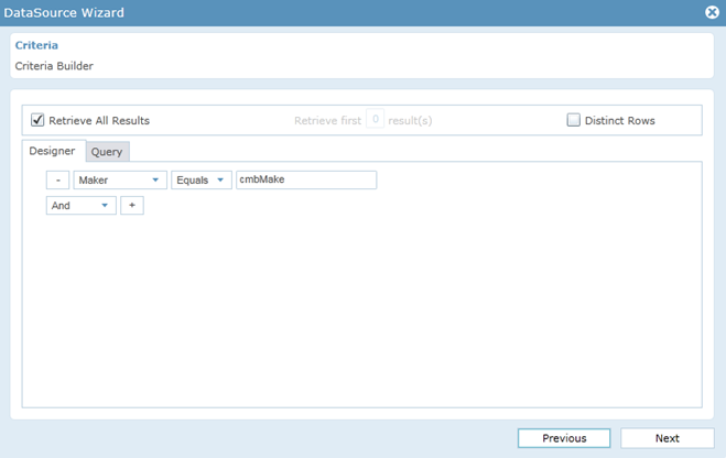
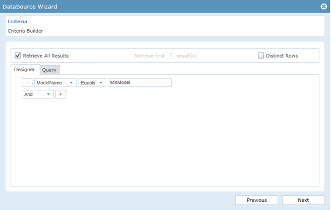
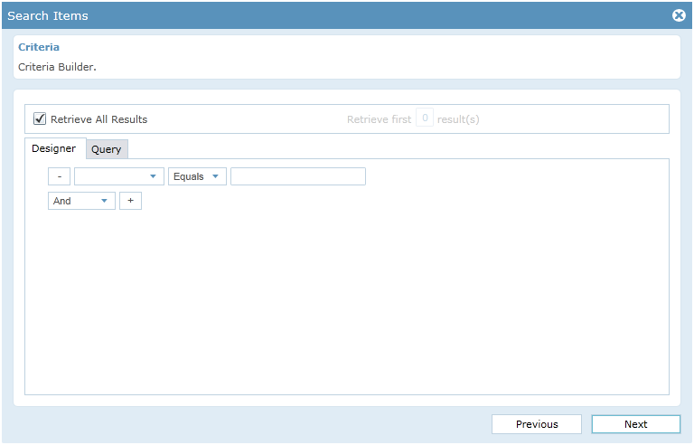
- Add the designer criteria in the criteria builder that should select the unique record in the List that matches the user identity criteria in the Data source and additional and/or Query clauses can be added. Click ‘Next’ to continue.
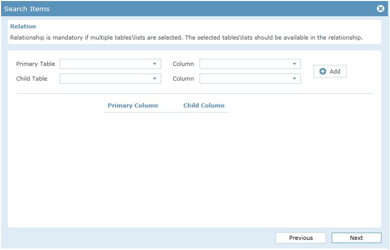
- If the selected lists needs any relationship then we can add their relations here. Click ‘Next’ to continue.
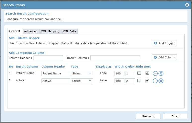
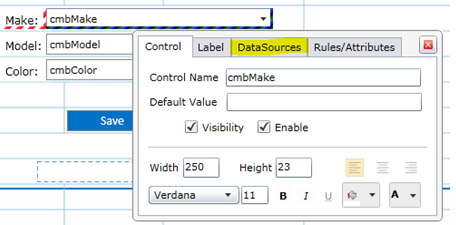
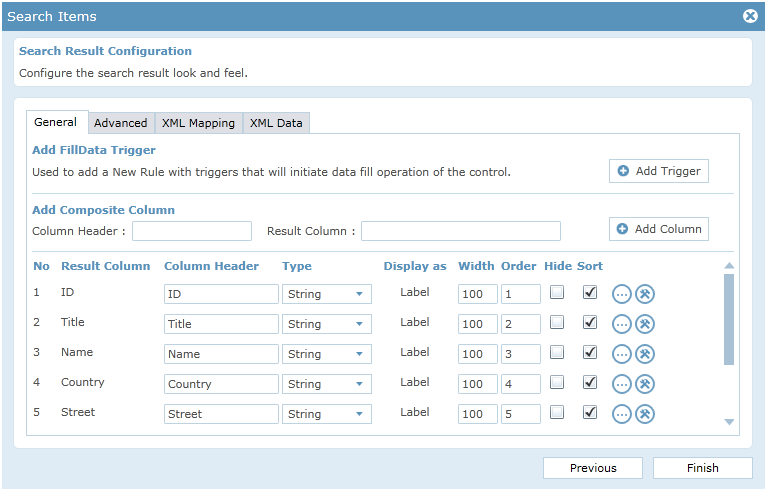
- We can change the look and feel of the search control.
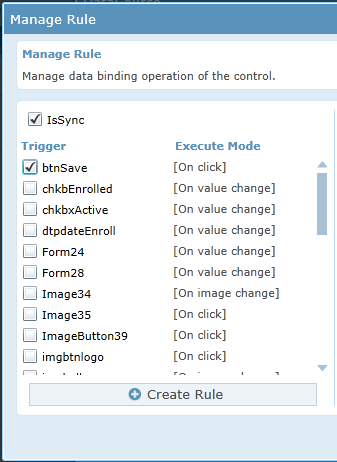
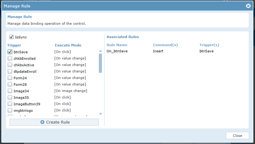
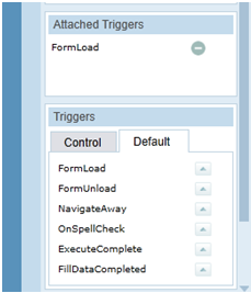
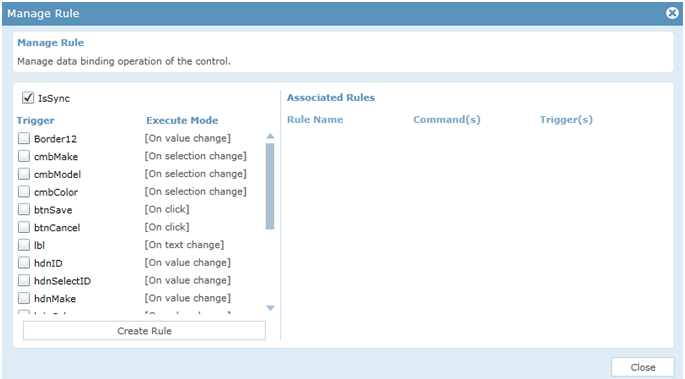
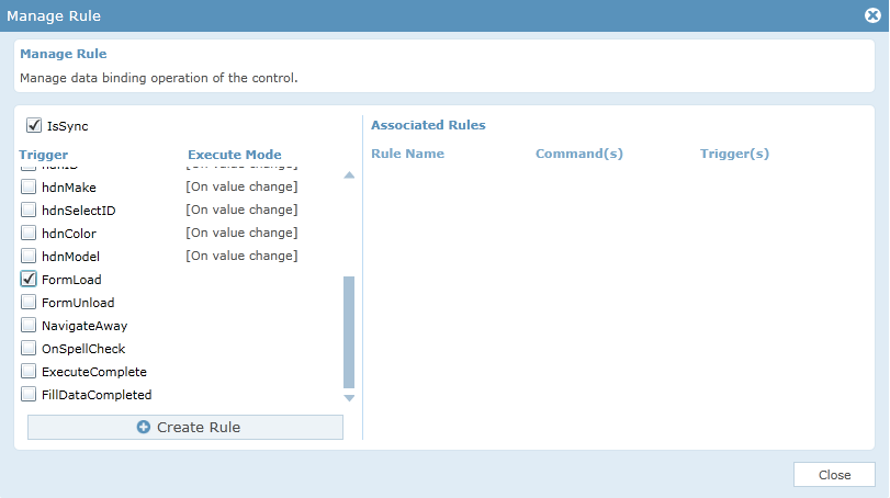
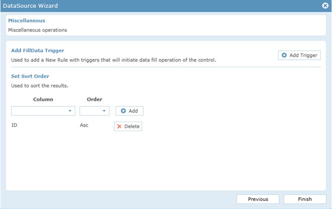
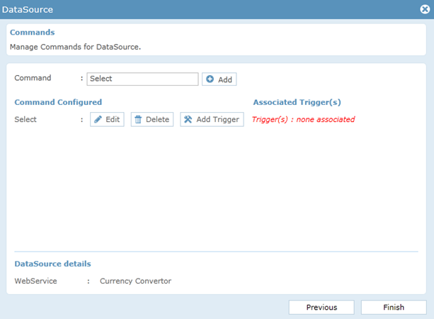
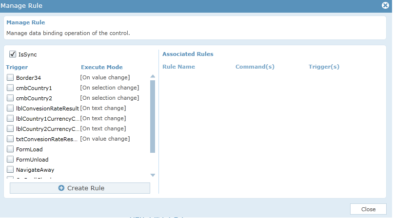
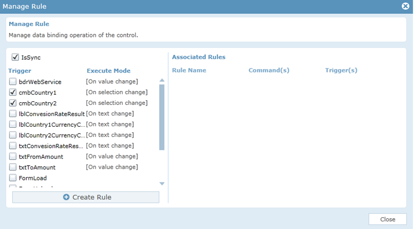
- Click ‘Add Trigger’ to add the trigger.
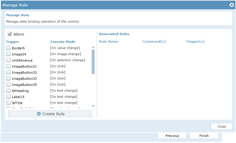
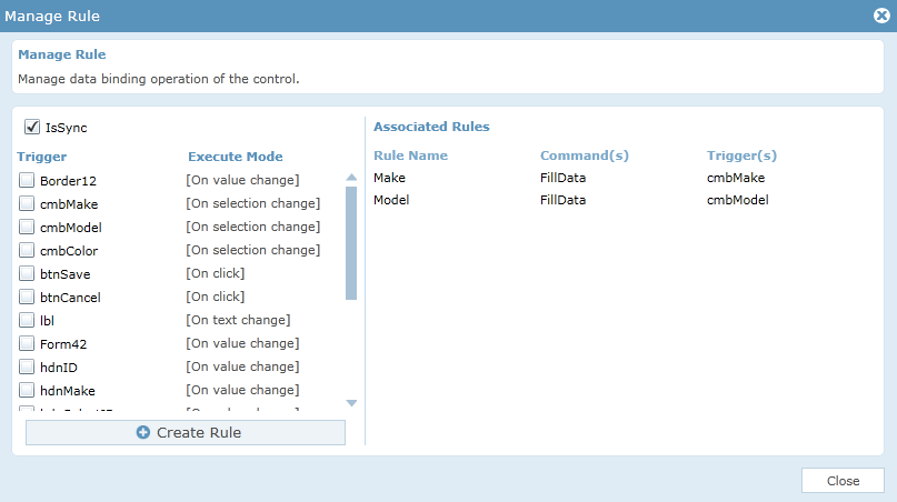
- We can select and add the trigger by clicking the check box corresponding to the control.
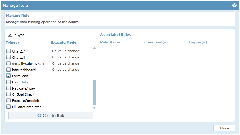
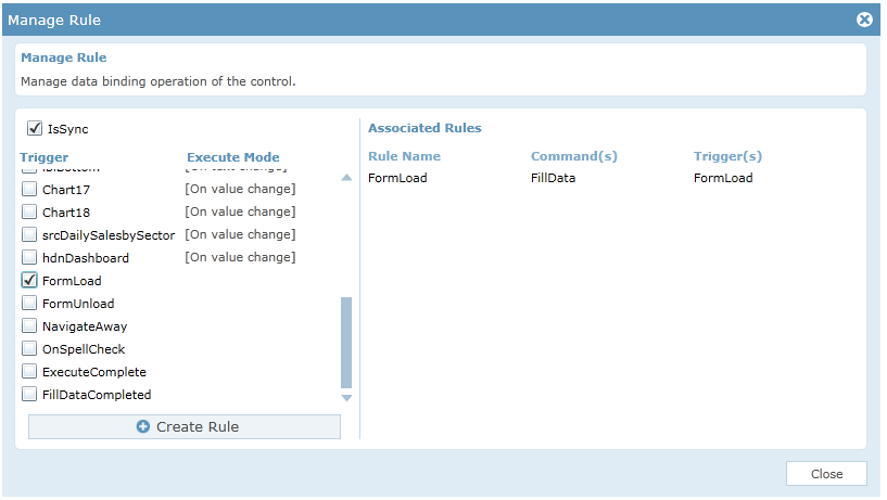
- Click ‘Create Rule’ will automatically create the FillData() rule for the search control with associated trigger.
- Click ‘Finish’ button to save and close the DataSource configuration process for the search control.
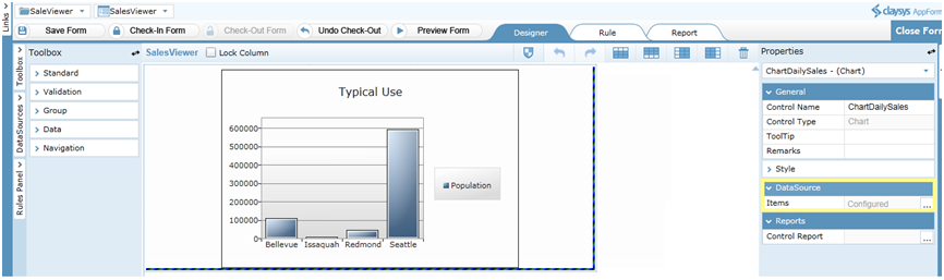
Following steps will explain about the DataSource configuration of Chart control:
Before configuring the chart control, a search control should be configured whose data has to be taken for mapping the chart control.
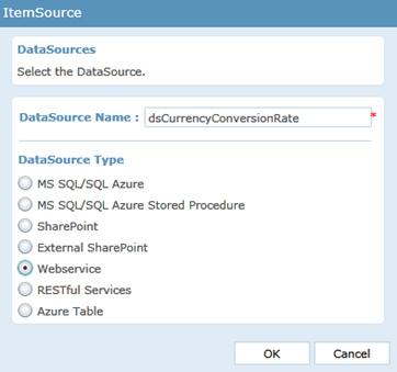
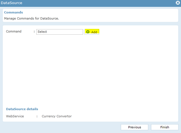
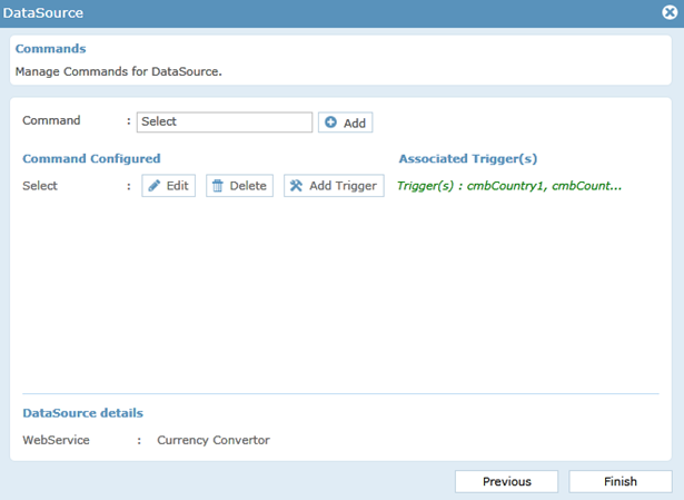
- Click on the Chart control and select the DataSource.
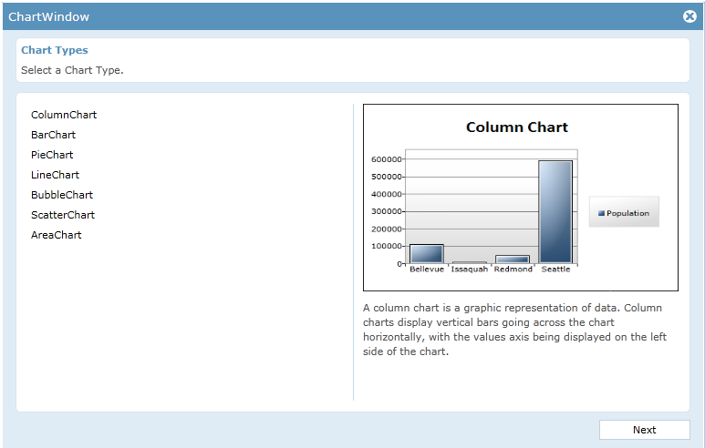
- A chart window appears. Select a suitable Chart type. Click ‘Next’ to continue.
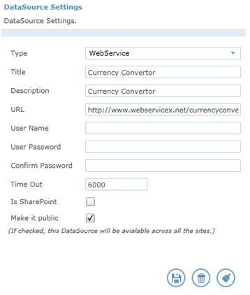
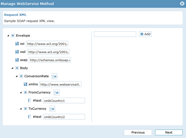
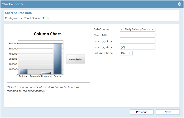
- A Chart window appears for configuring the Chart Source Data. Select the DataSource as a Search control whose data has to be taken for mapping the chart control. Add a Chart title and label the X and Y axis. Click ‘Next’ to continue.
- Chart window appears for configuring the Series title, Independent value path and Dependent value path. Click ‘OK’ to add the option.
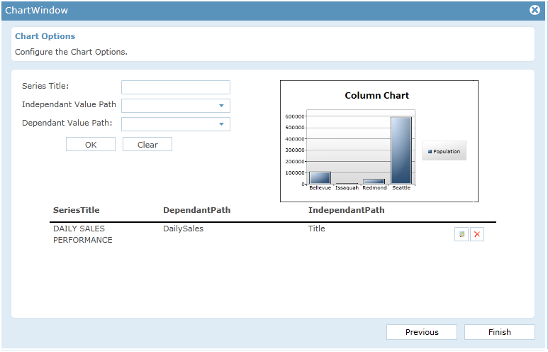
- Click ‘Finish’ button to save and close the DataSource configuration process for the Chart control.
Rules
The rules section is the most powerful section in the AppForms. The rules can be configured using the Rules Engine. Following are the rules associated with the application.
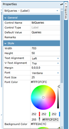
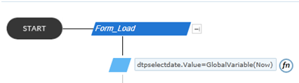
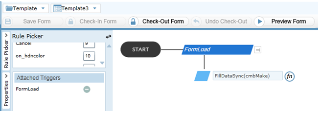
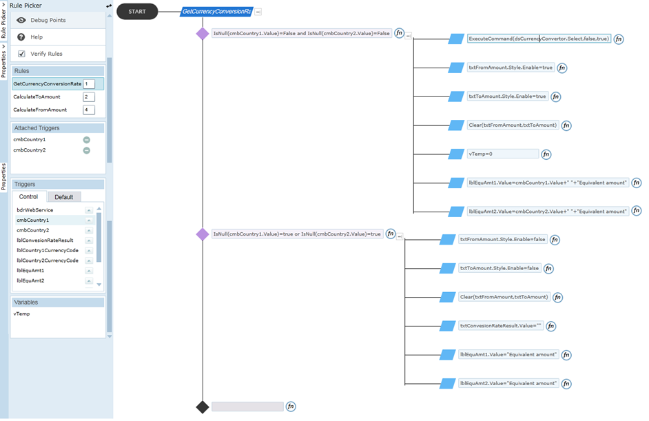
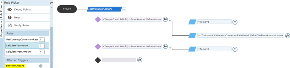
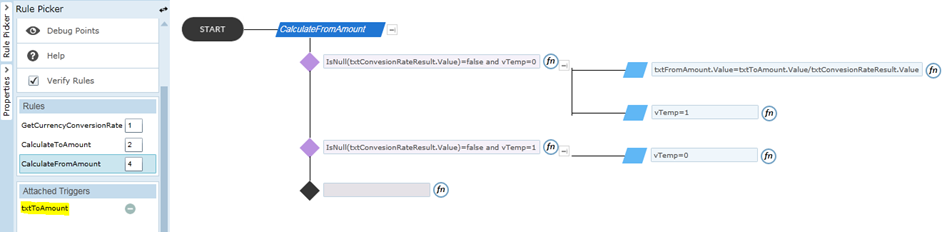
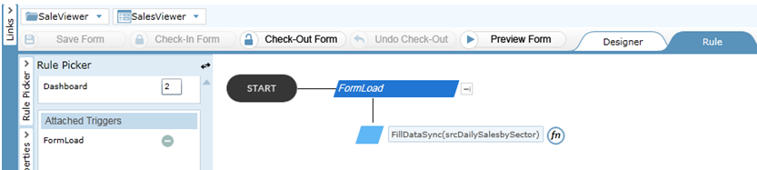
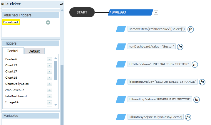
- The rule named ‘FormLoad’, fills the search control and set the values to label controls on ‘FormLoad’ as trigger.
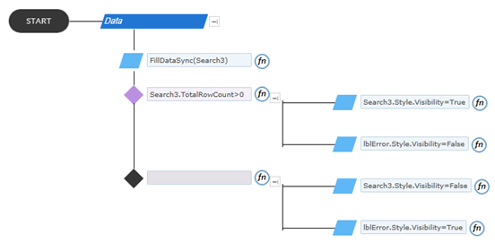
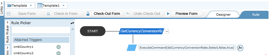
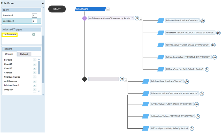
- The rule named ‘Dashboard’ fills the search control ‘srcDailySalesbySector’ and sets the values to the label controls based on the value in the combo box ‘cmbRevenue’, on ‘cmbRevenue’ as trigger. Depends on the values in the search control the Chart controls will be populated. This process is converted into concise, yet readily understood rule expression statements that represent the underlying execution logic of the form as shown in the figure.
How to use this template
Uploading List Templates
List templates that were downloaded to a file on the file system can be uploaded to the list template gallery. To perform the following steps, you must have Read permission to the folder or network share that contains the list template file. Before uploading the list template, it should be added to the list template gallery of the root site. Following steps will explain about how to add the list template in to the list template gallery.
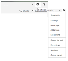
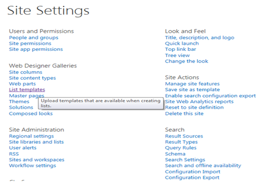
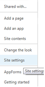
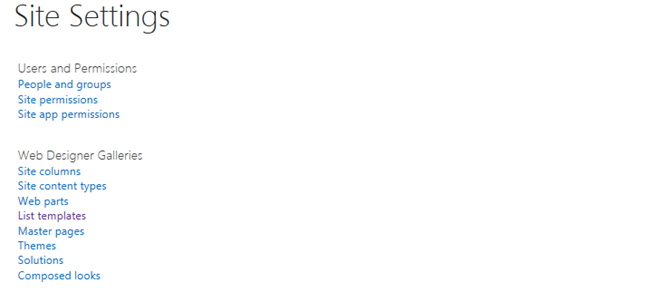
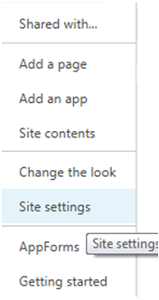
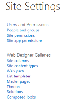
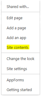
- On the Site Actions menu, click ‘Site Settings’.
- In the Galleries column, click List templates. This option appears only to users who have the Manage Lists permission. Site owners have this permission by default.
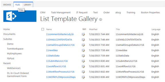
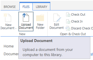
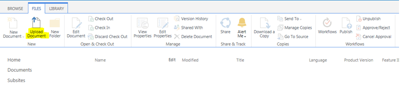
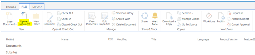
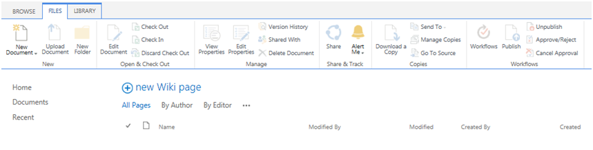
- The List Template Gallery page appears. Select Files tab and click ‘Upload Document’.
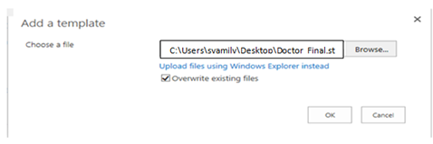
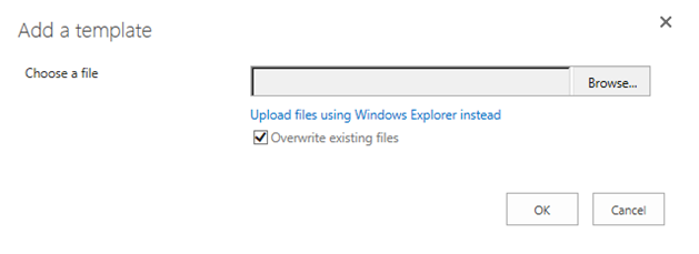
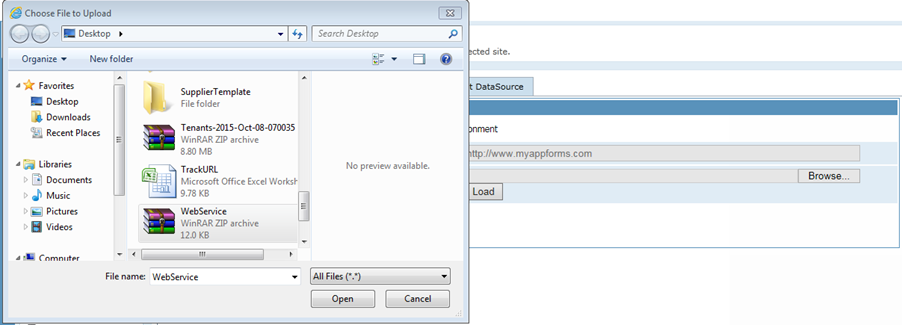
- Either type the path or file name (including the file extension) of the list template that you want to upload, or click ‘Browse’ to select the file. Choose whether to overwrite the existing files. By default, the ‘Overwrite existing files’ check box is selected.
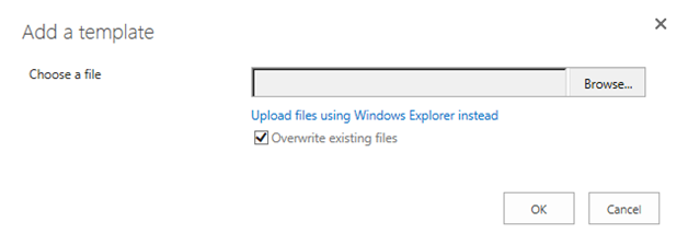
- Click ‘OK’ to choose the file.
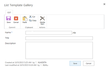
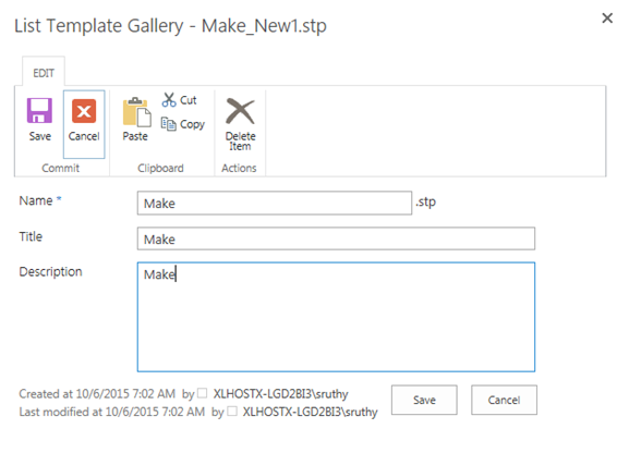
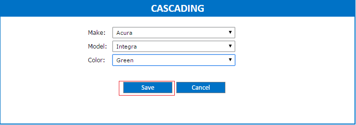
- A pop-up appears to edit the name, title and description of the list template.
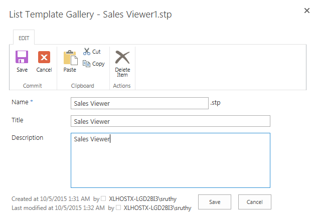
- Click ‘Save’ to include the list template into the list template gallery.
Once the list template is added to the list template gallery, we can create a new list using the list template uploaded. Following steps explains how to create a new list using list template.
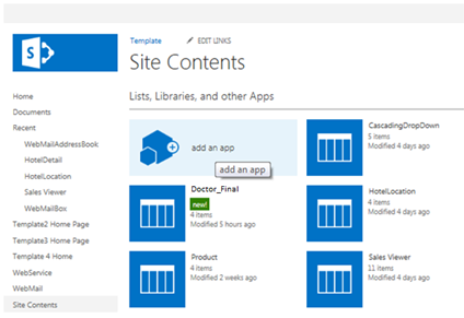
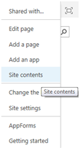
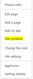
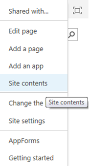
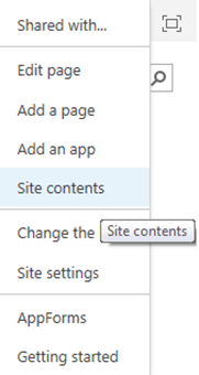
- From the Site Actions drop-down menu in the top right, select ‘Site Contents’ of your site.
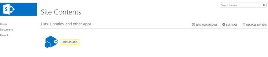
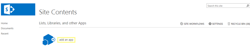
- Click ‘add an app’
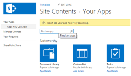
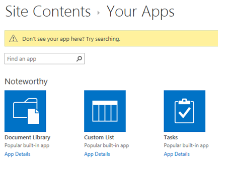
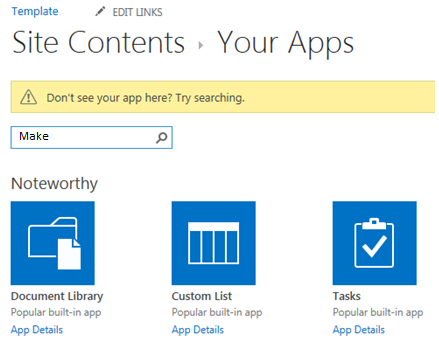
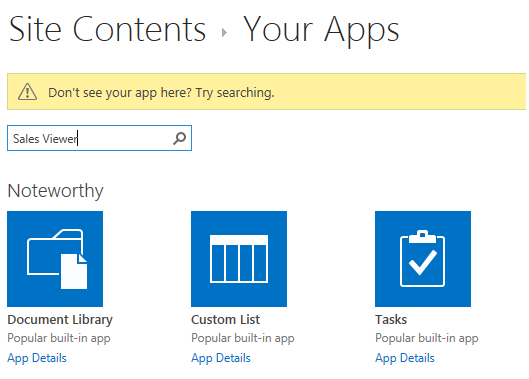
- Find the list template that was uploaded.
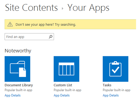
- Click on the list template to use for this site
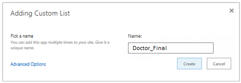
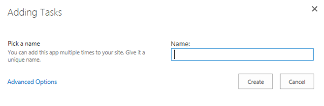
- Pick a name for the new list. We can add this app multiple times with a unique name.
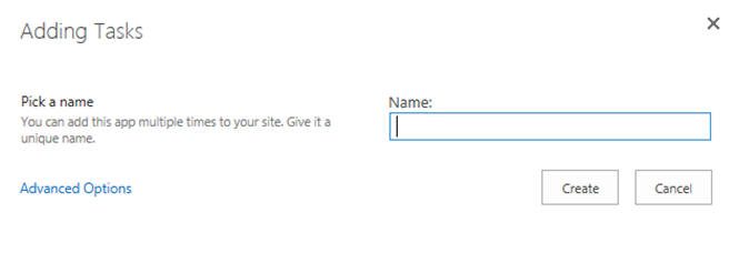
- Click on the ‘Create’ button. A list has now been created using the list template.
Import tenant
Following steps will explain about tenant import.
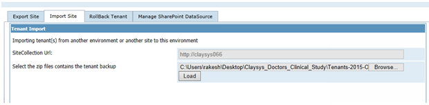
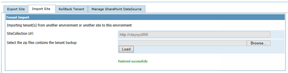
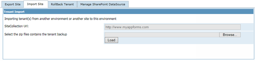
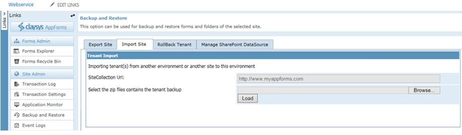
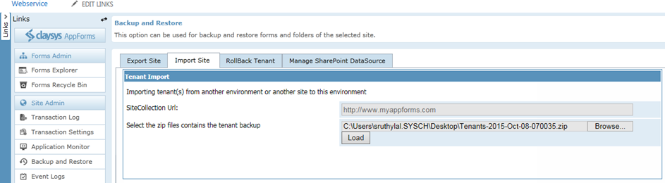
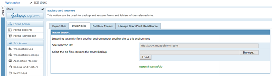
- Open the ‘Backup and Restore’ option in AppForms in the destination site and click on the ‘import site’ tab.
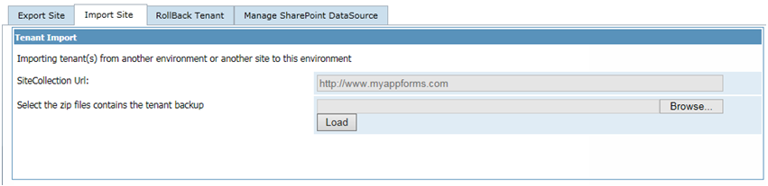
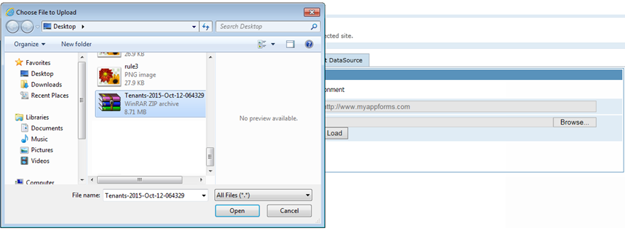
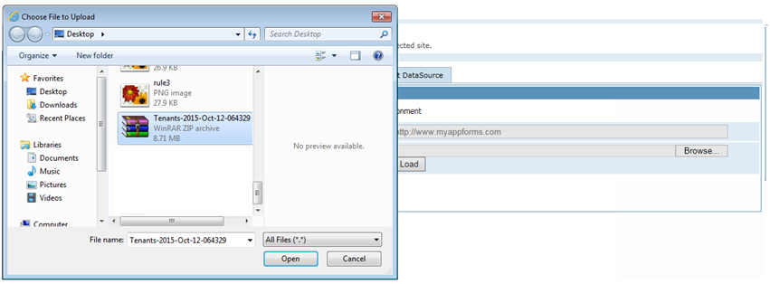
- Select the backup file we had saved from the source site.
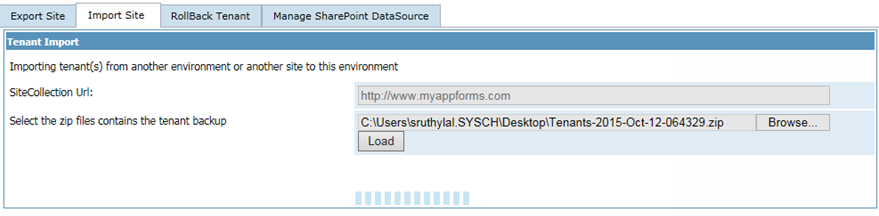
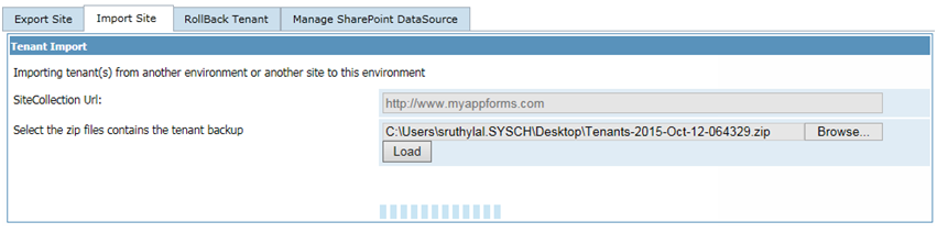
- Once the file is selected, click on the load button.
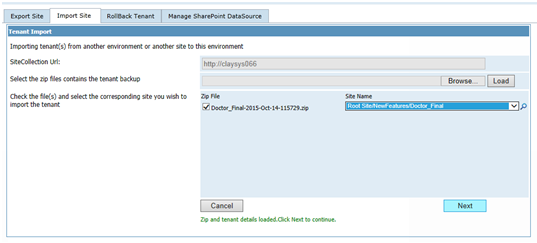
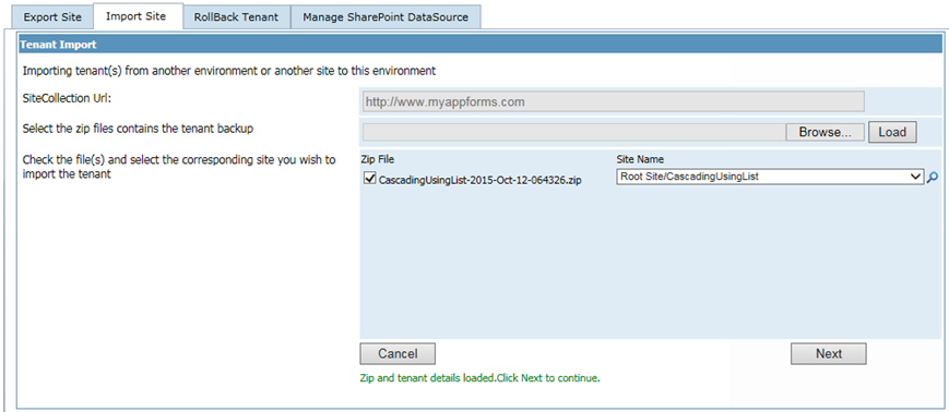
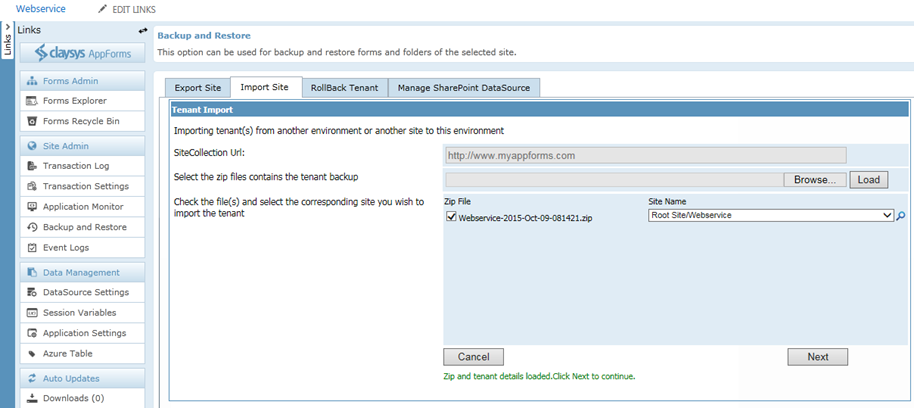
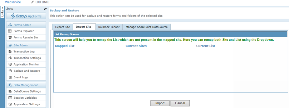
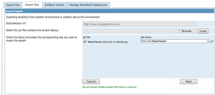
- This will show you the different sites that were exported from the source site. If there are more than one site content saved, then you can map each site in backup file to different sites in the current site. Select the required site content that needs to be restored and select the destination site in the current site as shown below. Once we are done with the backup mapping, click on the next button to proceed with the import.
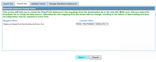
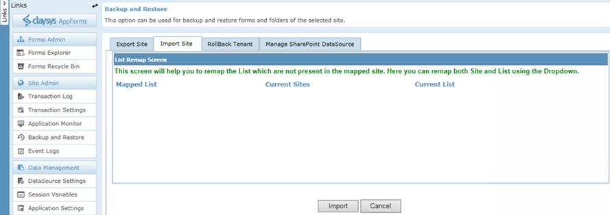
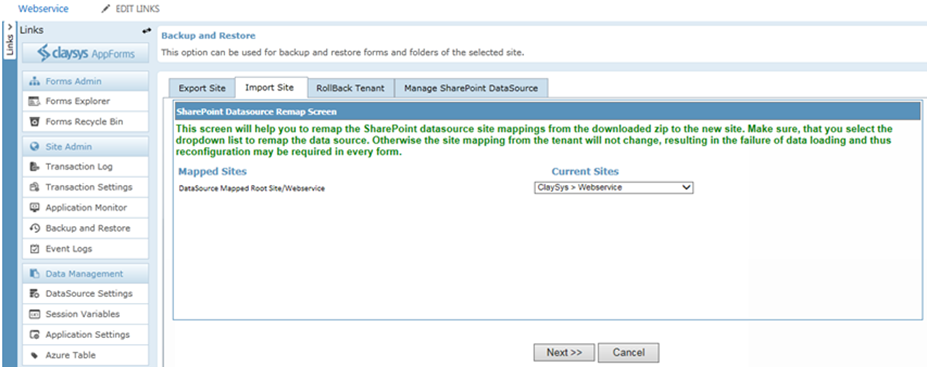
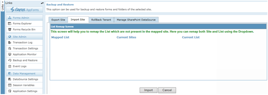
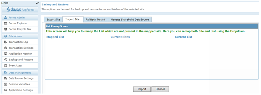
- Now we will have to remap the sites we had used in the source website to the actual site in the target site. The drop down will show you with the sites/sub sites to help you with the data source mapping. Click ‘Next’ to continue.
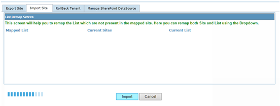
- Click ‘Import’ to continue.
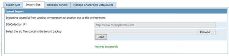
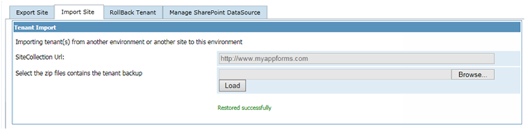
- This will import all the site content we had backed up from the source site and we are ready to work with the forms in the current site.
Create a Web Part Page
Forms can be embedded on any SharePoint page by using the ClaySys AppForms Web Part, to create a web part page, follow these steps:
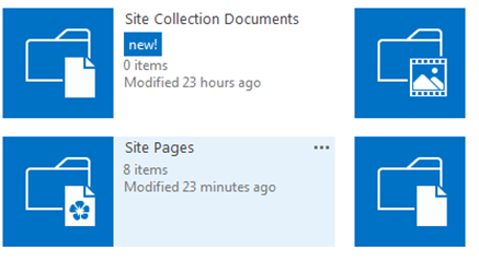
- Click on Site Settings Wheel in the upper right corner of your site and then select “Site Contents” Page.
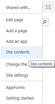
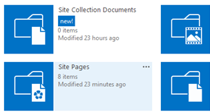
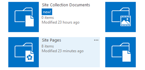
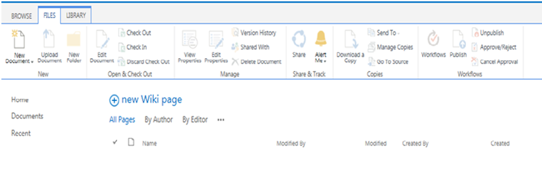
- Select “Site Pages” or simply pages library on Site Contents Page.
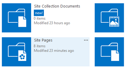
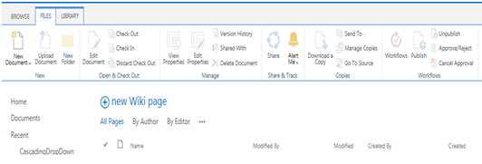
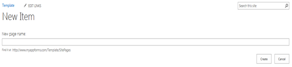
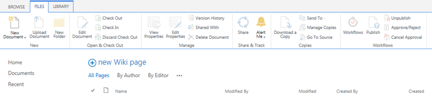
- Click on “New Wiki Page” to add new site page.
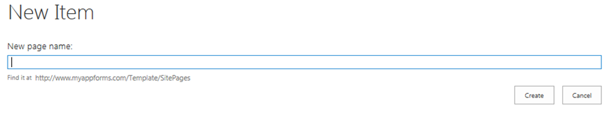
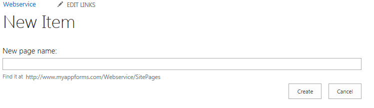
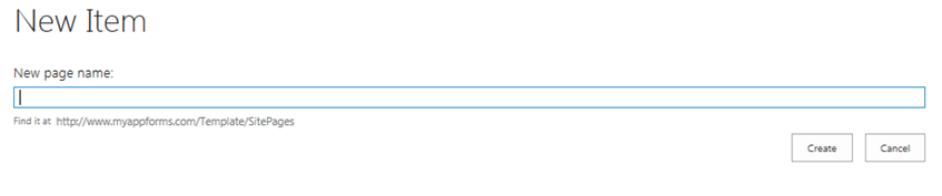
- Give the New page name into the pop-up window and click ‘Create’ to add new page.
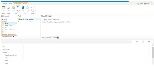
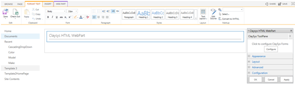
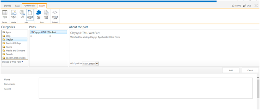
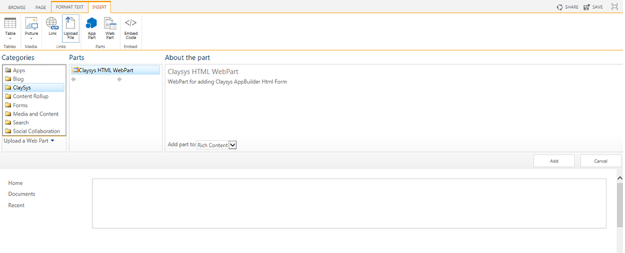
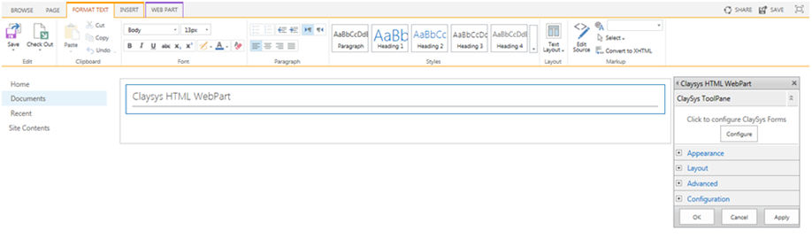
- To add a new web part, click on the ‘Insert’ tab and then click on the ‘Web Part’ button. Then select ClaySys -> ClaySys HTML Web Part.
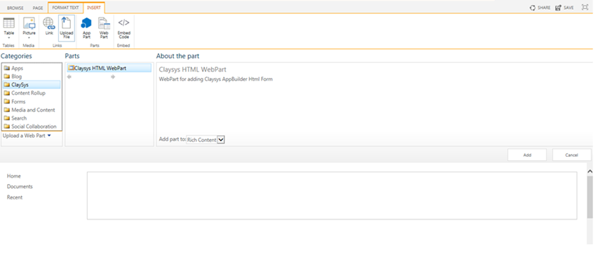
- Click ‘Add’ button to add the Web Part.
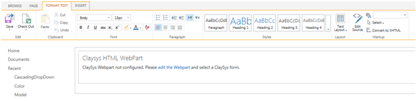
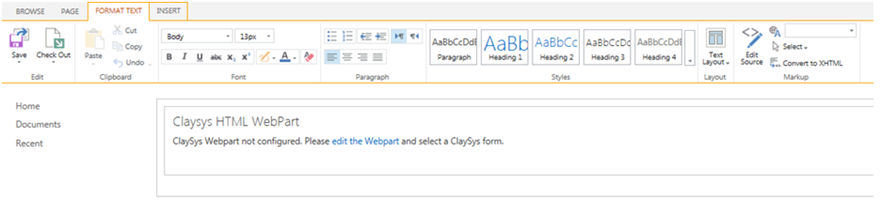
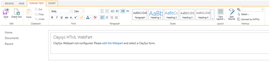
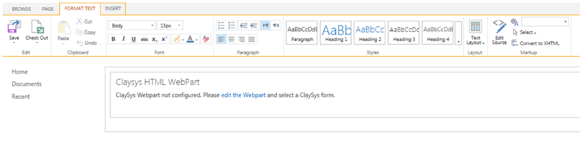
- Click on the ‘edit the Web part’ link to edit the page.
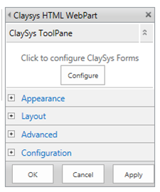
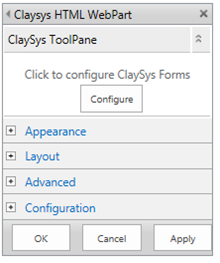
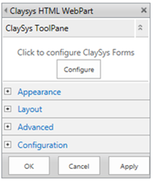
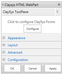
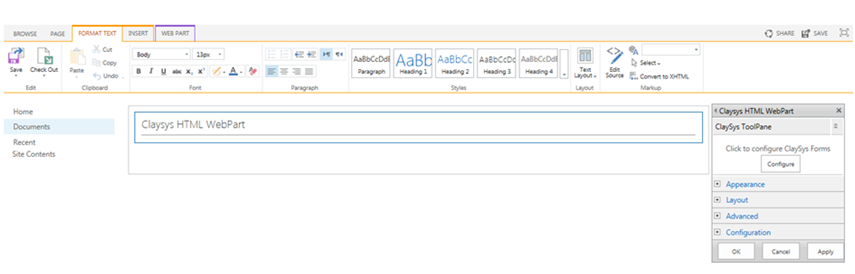
- A new pop-up window appears and here we can configure the ClaySys AppForms by clicking on the ‘Configure’ button.
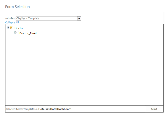
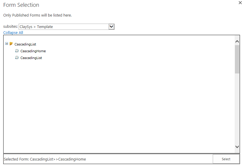
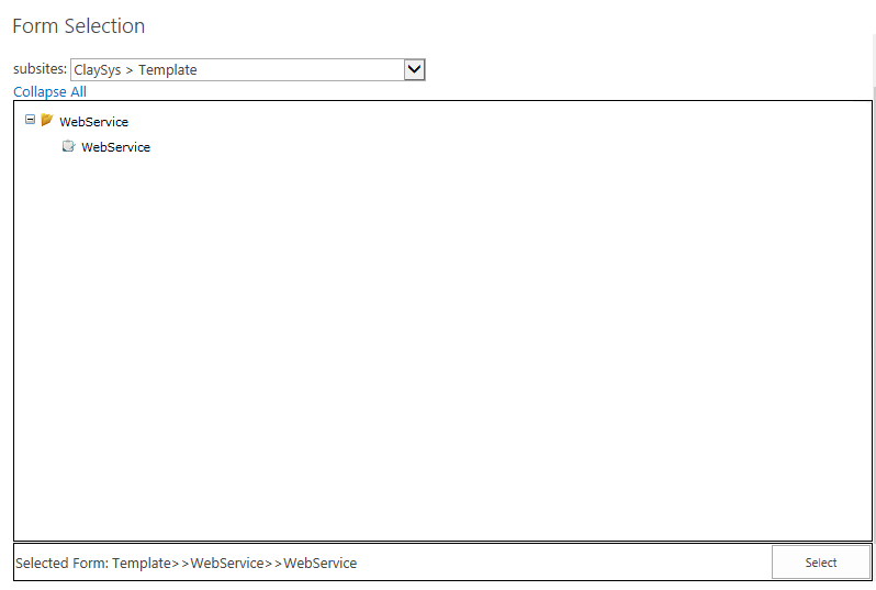
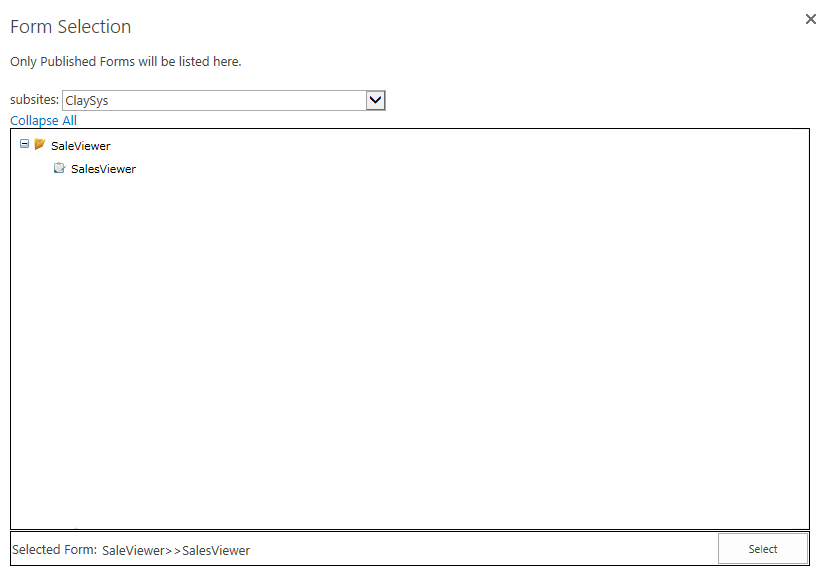
- Pop-up appears with listed published forms. We can select the appropriate form by click on the form and add the form by clicking on the ‘Select’ button.
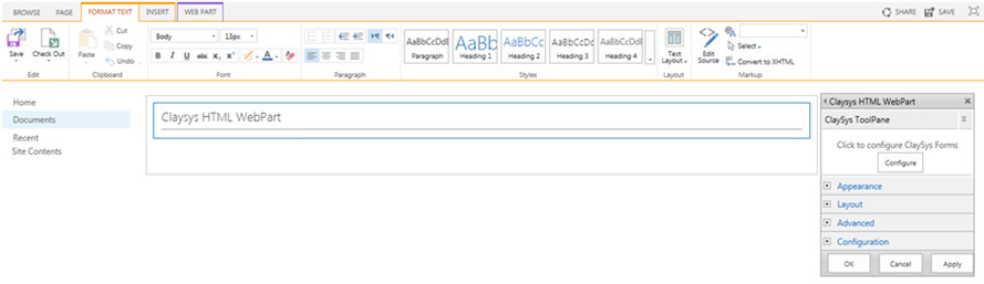
- Once the configuration is finished, click on the ‘Apply’ button to see the changes. Click ‘OK’ to continue.
- Click ‘Save’ button to save the changes.
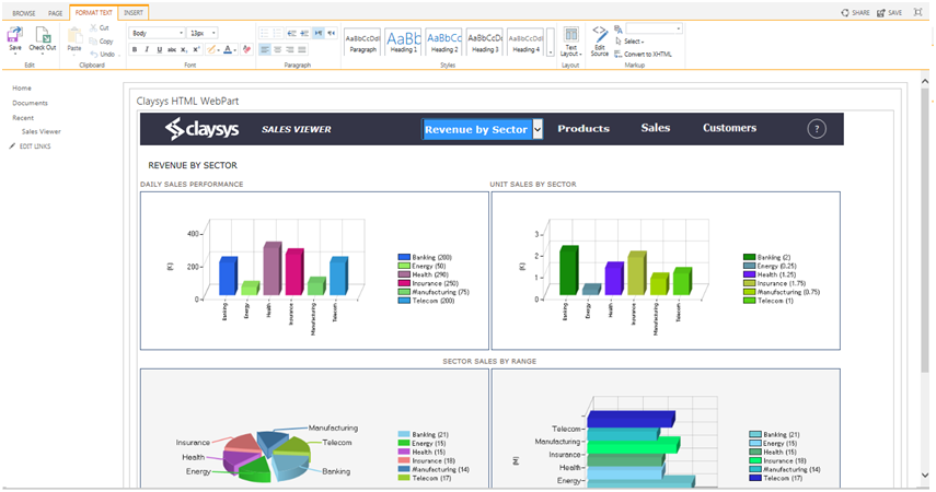
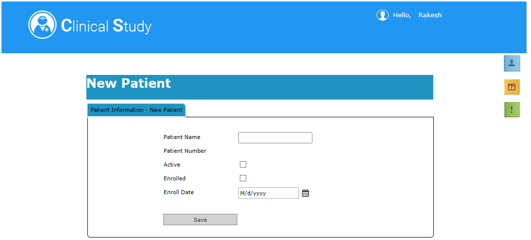
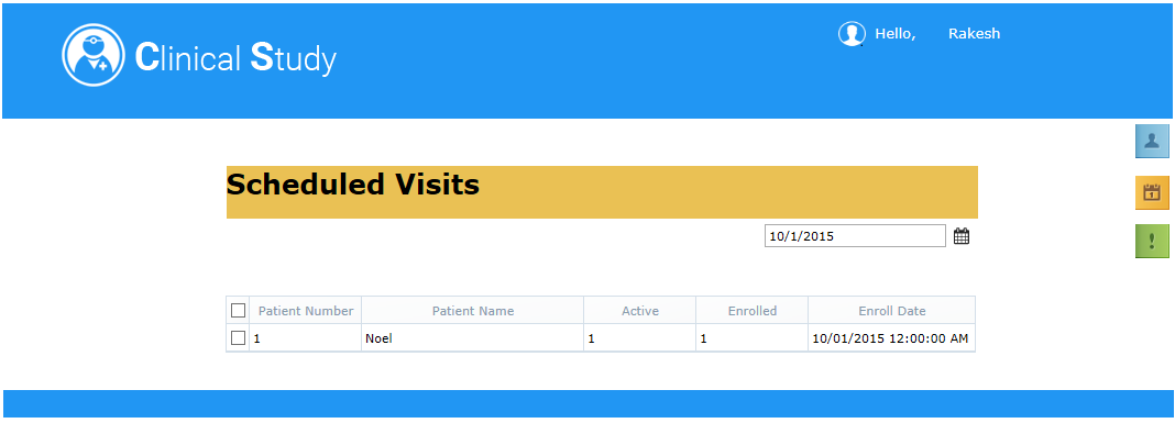
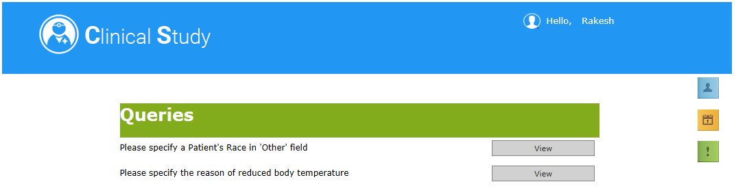
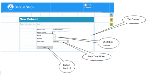
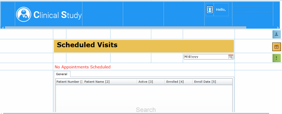
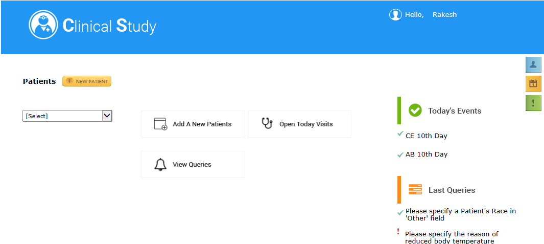
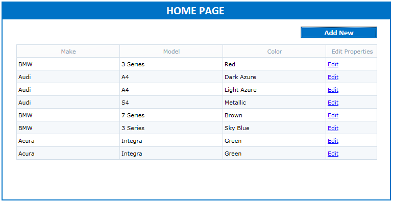
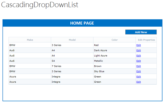
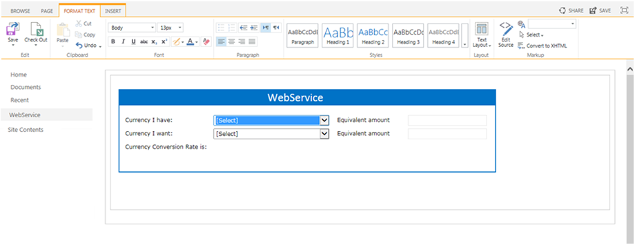
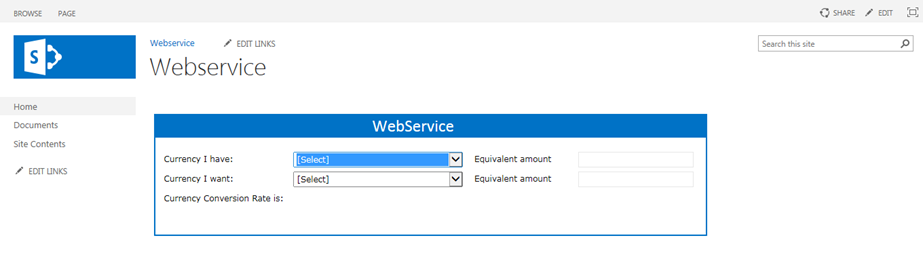
- Below figure shows the form after Web Part configuration.